


Đại lý Miki Pulley Vietnam
Lê Quốc Hoàng | Mr. |
Cellphone: 0911.77.19.19
Email: hoang@pitesco.com
Zalo: 0911.77.19.19
SPEED CHANGERS & REDUCERS
INVERTERS
ROTATION SPEED INDICATORS
TORQUE LIMITERS
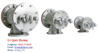
1.Hollow-shaft Speed Changers and Reducers – Hộp số/ Bộ biến tốc trục rỗng & Bộ giảm tốc trục rỗng
This series uses high-efficiency, compact hollow-shaft worm reducers as central modules that are combined with motors and belt-type stepless speed changers. They come in the geared motor RWM model, which combines a speed reducer with a motor, the RWM BS model, which uses a brake motor for its motor, and the RWP model, which includes a belt-type speed changer unit between the speed reducer and motor and can control speed. They all use B14 flange motors, so they are very compact.
List of Products:
Miki Pulley RW Mini Models- low-output hollow-shaft geared motors
· Use for Motor output 60 W to 90 W (4-pole)
· Power supply voltage Three-phase 200 V/50 Hz, 200 or 220 V/60 Hz
· Speed reduction ratios 1/10, 1/20, 1/30
· IP-54 structure
[Specifications]
|
Model |
Motor capacity [W] |
Poles |
Power supply Voltage[V]/Frequency[Hz] |
Speed reduction ratio |
Output shaft rotation speed[min-1] |
Output shaft torque [N・m] |
Mass[kg] |
|||
|
50Hz |
60Hz |
50Hz |
60Hz |
|||||||
|
RWM-006-30 |
-10 |
60 |
4 |
3-phase 200/50、200・220/60 |
1/10 |
135 |
163 |
3.4 |
2.9 |
3.6 |
|
-20 |
1/20 |
67.5 |
81.3 |
6.1 |
5.1 |
|||||
|
-30 |
1/30 |
45 |
54.2 |
8.2 |
6.8 |
|||||
|
RWM-009-30 |
-10 |
90 |
4 |
3-phase 200/50、200・220/60 |
1/10 |
133 |
160 |
5.2 |
4.3 |
4.1 |
|
-20 |
1/20 |
66.3 |
80 |
9.2 |
7.7 |
|||||
|
-30 |
1/30 |
44.2 |
53.3 |
12.3 |
10.3 |
|||||
· *The output rotation speed and output torque values are based on the rated motor load.
Miki Pulley RWM Models- hollow-shaft geared motors
· Use for Motor output 0.2 kW to 1.5 kW (4-pole)
· Power supply voltage Three-phase 200 V/50 Hz, 200 or 220 V/60 Hz
· Speed reduction ratios 1/10, 1/20, 1/30, 1/40, 1/50, 1/60
· flexibility in mounting on top, bottom, left or right
· Free-oil changes
[Specifications1]
|
Model |
Motor output[kW] |
Poles |
Power supply Voltage[V]/Frequency[Hz] |
Speed reducer frame number |
Speed reduction ratio |
Mass[kg] |
|||||
|
10 |
20 |
30 |
40 |
50 |
60 |
||||||
|
RWM-02-40-10-IE1 RWM-02-40-20-IE1 RWM-02-40-30-IE1 RWM-02-40-40-IE1 RWM-02-40-50-IE1 RWM-02-40-60-IE1 |
0.2 |
4 |
3-phase 200/50、200・220/60 |
40 |
1/10 |
1/20 |
1/30 |
1/40 |
1/50 |
1/60 |
8.8 |
|
RWM-04-50-10-IE1 RWM-04-50-20-IE1 RWM-04-50-30-IE1 RWM-04-50-40-IE1 RWM-04-50-50-IE1 RWM-04-50-60-IE1 |
0.4 |
4 |
3-phase 200/50、200・220/60 |
50 |
1/10 |
1/20 |
1/30 |
1/40 |
1/50 |
1/60 |
12 |
|
RWM-07-63N-10-IE3 RWM-07-63N-20-IE3 RWM-07-63N-30-IE3 RWM-07-63N-40-IE3 RWM-07-63N-50-IE3 RWM-07-63N-60-IE3 |
0.75 |
4 |
3-phase 200/50、200・220/60 |
63N |
1/10 |
1/20 |
1/30 |
1/40 |
1/50 |
1/60 |
23.2 |
|
RWM-15-75N-10-IE3 RWM-15-75N-20-IE3 RWM-15-75N-30-IE3 RWM-15-75N-40-IE3 RWM-15-75N-50-IE3 RWM-15-75N-60-IE3 |
1.5 |
4 |
3-phase 200/50、200・220/60 |
75N |
1/10 |
1/20 |
1/30 |
1/40 |
1/50 |
1/60 |
33 |
Miki Pulley RWM(BS) Models- hollow-shaft geared motors with brakes
· Use for Motor output 0.2 kW to 1.5 kW (4-pole)
· Power supply voltage Three-phase 200 V/50 Hz, 200 or 220 V/60 Hz
· Speed reduction ratios 1/10, 1/20, 1/30, 1/40, 1/50, 1/60
[Specifications]
|
Model |
Motor output[kW] |
Poles |
Power supply Voltage[V]/Frequency[Hz] |
Speed reducer frame number |
Speed reduction ratio |
Mass[kg] |
|||||
|
10 |
20 |
30 |
40 |
50 |
60 |
||||||
|
RWM-02BS-40-□ RWM-02BS-40-10 RWM-02BS-40-20 RWM-02BS-40-30 RWM-02BS-40-40 RWM-02BS-40-50 RWM-02BS-40-60 |
0.2 |
4 |
3-phase 200/50、200・220/60 |
40 |
1/10 |
1/20 |
1/30 |
1/40 |
1/50 |
1/60 |
8.3 |
|
RWM-04BS-50-□ RWM-04BS-50-10 RWM-04BS-50-20 RWM-04BS-50-30 RWM-04BS-50-40 RWM-04BS-50-50 RWM-04BS-50-60 |
0.4 |
4 |
3-phase 200/50、200・220/60 |
50 |
1/10 |
1/20 |
1/30 |
1/40 |
1/50 |
1/60 |
10.7 |
|
RWM-07BS-63N-□-IE3 RWM-07BS-63N-10-IE3 RWM-07BS-63N-20-IE3 RWM-07BS-63N-30-IE3 RWM-07BS-63N-40-IE3 RWM-07BS-63N-50-IE3 RWM-07BS-63N-60-IE3 |
0.75 |
4 |
3-phase 200/50、200・220/60 |
63N |
1/10 |
1/20 |
1/30 |
1/40 |
1/50 |
1/60 |
24 |
|
RWM-15BS-75N-□-IE3 RWM-15BS-75N-10-IE3 RWM-15BS-75N-20-IE3 RWM-15BS-75N-30-IE3 RWM-15BS-75N-40-IE3 RWM-15BS-75N-50-IE3 RWM-15BS-75N-60-IE3 |
1.5 |
4 |
3-phase 200/50、200・220/60 |
75N |
1/10 |
1/20 |
1/30 |
1/40 |
1/50 |
1/60 |
31 |
Miki Pulley RWP Models - belt-type stepless speed changer
· Use for Motor output 0.2 kW to 1.5 kW (4-pole)
· Power supply voltage Three-phase 200 V/50 Hz, 200 or 220 V/60 Hz
· Speed reduction ratios 1/10, 1/20, 1/30, 1/40, 1/50, 1/60
· Lighter & smaller
[Specifications]
|
Model |
Motor output[kW] |
Poles |
Power supply Voltage[V]/Frequency[Hz] |
Speed reducer frame number |
Speed reduction ratio |
Mass[kg] |
|||||
|
10 |
20 |
30 |
40 |
50 |
60 |
||||||
|
RWP-02-□-40-□-IE1 RWP-02-C-40-10-IE1 RWP-02-C-40-20-IE1 RWP-02-C-40-30-IE1 RWP-02-C-40-40-IE1 RWP-02-C-40-50-IE1 RWP-02-C-40-60-IE1 RWP-02-Z-40-10-IE1 RWP-02-Z-40-20-IE1 RWP-02-Z-40-30-IE1 RWP-02-Z-40-40-IE1 RWP-02-Z-40-50-IE1 RWP-02-Z-40-60-IE1 |
0.2 |
4 |
3-phase 200/50、200・220/60 |
40 |
1/10 |
1/20 |
1/30 |
1/40 |
1/50 |
1/60 |
10.7 |
|
RWP-04-□-50-□-IE1 RWP-04-C-50-10-IE1 RWP-04-C-50-20-IE1 RWP-04-C-50-30-IE1 RWP-04-C-50-40-IE1 RWP-04-C-50-50-IE1 RWP-04-C-50-60-IE1 RWP-04-Z-50-10-IE1 RWP-04-Z-50-20-IE1 RWP-04-Z-50-30-IE1 RWP-04-Z-50-40-IE1 RWP-04-Z-50-50-IE1 RWP-04-Z-50-60-IE1 |
0.4 |
4 |
3-phase 200/50、200・220/60 |
50 |
1/10 |
1/20 |
1/30 |
1/40 |
1/50 |
1/60 |
15.4 |
|
RWP-07-□-63N-□-IE3 RWP-07-Z-63N-10-IE3 RWP-07-Z-63N-20-IE3 RWP-07-Z-63N-30-IE3 RWP-07-Z-63N-40-IE3 RWP-07-Z-63N-50-IE3 RWP-07-Z-63N-60-IE3 RWP-07-C-63N-10-IE3 RWP-07-C-63N-20-IE3 RWP-07-C-63N-30-IE3 RWP-07-C-63N-40-IE3 RWP-07-C-63N-50-IE3 RWP-07-C-63N-60-IE3 |
0.75 |
4 |
3-phase 200/50、200・220/60 |
63N |
1/10 |
1/20 |
1/30 |
1/40 |
1/50 |
1/60 |
27.3 |
|
RWP-15-□-75N-□-IE3 RWP-15-Z-75N-10-IE3 RWP-15-Z-75N-20-IE3 RWP-15-Z-75N-30-IE3 RWP-15-Z-75N-40-IE3 RWP-15-Z-75N-50-IE3 RWP-15-Z-75N-60-IE3 RWP-15-C-75N-10-IE3 RWP-15-C-75N-20-IE3 RWP-15-C-75N-30-IE3 RWP-15-C-75N-40-IE3 RWP-15-C-75N-50-IE3 RWP-15-C-75N-60-IE3 |
1.5 |
4 |
3-phase 200/50、200・220/60 |
75N |
1/10 |
1/20 |
1/30 |
1/40 |
1/50 |
1/60 |
39.9 |
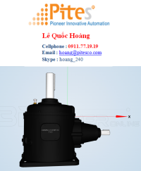
2.Solid-shaft Speed Changers and Reducers – Hộp số/ Bộ biến tốc trục đặc & Bộ giảm tốc trục đặc
This series uses high-efficiency, compact solid-shaft worm reducers as central modules that are combined with motors and belt-type stepless speed changers. They come in the geared motor AXM model, which combines a speed reducer with a motor, and the AXP model, which includes a belt-type speed changer unit between the speed reducer and motor and can control speed. They all use B14 flange motors, so they are very compact.
List of Products:
AXM Models
These are solid-shaft geared motors for motor outputs of 0.2 kW to 1.5 kW (4-pole).They use B14 flange motors for a very compact design that saves space in mechanical devices.
· Motor output 0.2 kW to 1.5 kW (4-pole)
· Power supply voltage Three-phase 200 V/50 Hz, 200 or 220 V/60 Hz
· Speed reduction ratios 1/10, 1/20, 1/30, 1/40, 1/50, 1/60
[Specifications]
|
Model |
Motor output[kW] |
Poles |
Power supply Voltage[V]/Frequency[Hz] |
Speed reducer frame number |
Speed reduction ratio |
Mass[kg] |
|||||
|
10 |
20 |
30 |
40 |
50 |
60 |
||||||
|
AXM-02-50N-□-□-IE1 AXM-02-50N-10-R-IE1 AXM-02-50N-20-R-IE1 AXM-02-50N-30-R-IE1 AXM-02-50N-40-R-IE1 AXM-02-50N-50-R-IE1 AXM-02-50N-60-R-IE1 AXM-02-50N-10-L-IE1 AXM-02-50N-20-L-IE1 AXM-02-50N-30-L-IE1 AXM-02-50N-40-L-IE1 AXM-02-50N-50-L-IE1 AXM-02-50N-60-L-IE1 |
0.2 |
4 |
3-phase 200/50、200・220/60 |
50 |
1/10 |
1/20 |
1/30 |
1/40 |
1/50 |
1/60 |
14 |
|
AXM-04-60N-□-□-IE1 AXM-04-60N-10-R-IE1 AXM-04-60N-20-R-IE1 AXM-04-60N-30-R-IE1 AXM-04-60N-40-R-IE1 AXM-04-60N-50-R-IE1 AXM-04-60N-60-R-IE1 AXM-04-60N-10-L-IE1 AXM-04-60N-20-L-IE1 AXM-04-60N-30-L-IE1 AXM-04-60N-40-L-IE1 AXM-04-60N-50-L-IE1 AXM-04-60N-60-L-IE1 |
0.4 |
4 |
3-phase 200/50、200・220/60 |
60 |
1/10 |
1/20 |
1/30 |
1/40 |
1/50 |
1/60 |
17 |
|
AXM-07-70N-□-□-IE3 AXM-07-70N-10-R-IE3 AXM-07-70N-20-R-IE3 AXM-07-70N-30-R-IE3 AXM-07-70N-40-R-IE3 AXM-07-70N-50-R-IE3 AXM-07-70N-60-R-IE3 AXM-07-70N-10-L-IE3 AXM-07-70N-20-L-IE3 AXM-07-70N-30-L-IE3 AXM-07-70N-40-L-IE3 AXM-07-70N-50-L-IE3 AXM-07-70N-60-L-IE3 |
0.75 |
4 |
3-phase 200/50、200・220/60 |
70 |
1/10 |
1/20 |
1/30 |
1/40 |
1/50 |
1/60 |
32 |
|
AXM-15-80N-□-□-IE3 AXM-15-80N-10-R-IE3 AXM-15-80N-20-R-IE3 AXM-15-80N-30-R-IE3 AXM-15-80N-40-R-IE3 AXM-15-80N-50-R-IE3 AXM-15-80N-60-R-IE3 AXM-15-80N-10-L-IE3 AXM-15-80N-20-L-IE3 AXM-15-80N-30-L-IE3 AXM-15-80N-40-L-IE3 AXM-15-80N-50-L-IE3 AXM-15-80N-60-L-IE3 |
1.5 |
4 |
3-phase 200/50、200・220/60 |
80 |
1/10 |
1/20 |
1/30 |
1/40 |
1/50 |
1/60 |
43 |
AXP Models
These models add a belt-type stepless speed changer to an AXM solid-shaft geared motor. They are about 20% lighter and smaller than our previous belt-type stepless speed changer (0.4-kW model).They can also operate at high torque while at low speeds (compared to the 0.4-kW model), not a traditional strength of inverters.
· Motor output 0.2 kW to 1.5 kW (4-pole)
· Power supply voltage Three-phase 200 V/50 Hz, 200 V or 220 V/60 Hz
· Speed reduction ratios 1/10, 1/20, 1/30, 1/40, 1/50, 1/60
[Specifications]
|
Model |
Motor output[kW] |
Poles |
Power supply Voltage[V]/Frequency[Hz] |
Speed reducer frame number |
Speed reduction ratio |
Mass[kg] |
|||||
|
10 |
20 |
30 |
40 |
50 |
60 |
||||||
|
AXP-02-C-50N-□-□-IE1 AXP-02-Z-50N-□-□-IE1 |
0.2 |
4 |
3-phase 200/50、200・220/60 |
50 |
1/10 |
1/20 |
1/30 |
1/40 |
1/50 |
1/60 |
15 |
|
AXP-04-C-60N-□-□-IE1 AXP-04-Z-60N-□-□-IE1 |
0.4 |
4 |
3-phase 200/50、200・220/60 |
60 |
1/10 |
1/20 |
1/30 |
1/40 |
1/50 |
1/60 |
26 |
|
AXP-07-C-70N-□-□-IE3 AXP-07-Z-70N-□-□-IE3 |
0.75 |
4 |
3-phase 200/50、200・220/60 |
70 |
1/10 |
1/20 |
1/30 |
1/40 |
1/50 |
1/60 |
36 |
|
AXP-15-C-80N-□-□-IE3 AXP-15-Z-80N-□-□-IE3 |
1.5 |
4 |
3-phase 200/50、200・220/60 |
80 |
1/10 |
1/20 |
1/30 |
1/40 |
1/50 |
1/60 |
52 |
3.Belt-type Stepless Speed Changer Units – Hộp số/ Bộ biến tốc vô cấp kiểu dây đai
These units change speeds without changing the distance between shafts by making the belt pitch diameter of one variable-speed pulley track the belt pitch diameter of another variable-speed pulley when its belt pitch diameter is changed. Since speed can be changed without changing the distance between shafts, more compact designs are possible, mounting is simple, and ease of use is exceptional. They can be combined with motor/speed reducer and electromagnetic clutches and brakes can also be built in. These units are easy to maintain and belt-type power transmission is efficient, helping to save energy.
List of Products:
Miki Pulley ANW (NHN/PMN) Types- Speed Changer Unit/ Gearbox
· Motor output 0.2 kW to 3.7 kW (4-pole)
· Power supply voltage Three-phase 200 V/50 Hz, 200 or 220 V/60 Hz
· Speed reduction ratios 1/10, 1/20, 1/30, 1/40, 1/50, 1/60
[Specifications]
|
Model |
Motor output[kW] |
Poles |
Power supply Voltage[V] /Frequency[Hz] |
Speed change ratio |
Speed changer in use |
Belt model in use |
Speed reducers |
|
|
Motor side speed changer model |
Machine side speed changer model |
|||||||
|
ANW-02NHN |
0.2 |
4 |
3-phase 200/50、200・220/60 |
1:4 |
AK-90-AN-11 |
PE-106-AN-12H |
1022V196S |
NHN-50 |
|
ANW-04NHN |
0.4 |
4 |
3-phase 200/50、200・220/60 |
1:4 |
AK-106-AN-14N |
PE-125-AN-15H |
1422V236S |
NHN-60 |
|
ANW-07NHN |
0.75 |
4 |
3-phase 200/50、200・220/60 |
1:4 |
AK-125-AN-19N |
PE-150N-AN-18H |
1422V270S |
NHN-70 |
|
ANW-15NHN |
1.5 |
4 |
3-phase 200/50、200・220/60 |
1:4 |
AK-150-AN-24N |
PE-180N-AN-22H |
1922V338S |
NHN-80 |
|
ANW-22PMN |
2.2 |
4 |
3-phase 200/50、200・220/60 |
1:4 |
AK-160-AN-28N |
PE-190N-AN-25H |
2322V341 |
N-PRM-25 |
|
ANW-37PMN |
3.7 |
4 |
3-phase 200/50、200・220/60 |
1:4 |
AK-180-AN-28N |
PE-212N-AN-30H |
2322V387S |
N-PRM-30 |
Miki Pulley ANW (NKN) Types- Speed Changer Unit/ Gearbox
· Motor output 0.2 kW to 1.5 kW (4-pole)
· Power supply voltage Three-phase 200 V/50 Hz, 200 or 220 V/60 Hz
· Speed reduction ratios 1/10, 1/20, 1/30, 1/40, 1/50, 1/60
[Specifications]
|
Model |
Motor output[kW] |
Poles |
Power supply Voltage[V]/Frequency[Hz] |
Speed change ratio |
Speed changer in use |
Belt model in use |
Speed reducers |
Mass[kg] |
|
|
Motor side speed changer model |
Machine side speed changer model |
||||||||
|
ANW-02NKN |
0.2 |
4 |
3-phase 200/50、200・220/60 |
1:4 |
AK-90-AN-11 |
PE-106-AN-12H |
1022V196S |
NKN-50 |
22 |
|
ANW-04NKN |
0.4 |
4 |
3-phase 200/50、200・220/60 |
1:4 |
AK-106-AN-14N |
PE-125-AN-15H |
1422V236S |
NKN-60 |
31 |
|
ANW-07NKN |
0.75 |
4 |
3-phase 200/50、200・220/60 |
1:4 |
AK-125-AN-19N |
PE-150N-AN-18H |
1422V270S |
NKN-70 |
52 |
|
ANW-15NKN |
1.5 |
4 |
3-phase 200/50、200・220/60 |
1:4 |
AK-150-AN-24N |
PE-180N-AN-22H |
1922V338S |
NKN-80 |
83 |
Miki Pulley ANG Models- Speed Changer Unit/ Gearbox
· Motor output 0.2 kW to 1.5 kW (4-pole)
· Power supply voltage Three-phase 200 V/50 Hz, 200 or 220 V/60 Hz
· Speed reduction ratios A: 1/5 to 1/25, B: 1/30 to 1/80
[Specifications]
|
Model |
Motor output[kW] |
Poles |
Power supply Voltage[V]/Frequency[Hz] |
Speed change ratio |
Speed changer in use |
Belt model in use |
Speed reducers |
|
|
Motor side speed changer model |
Machine side speed changer model |
|||||||
|
ANG-02GDN |
0.2 |
4 |
3-phase 200/50、200・220/60 |
1:4 |
AK-90-AN-11 |
PE-106-AN-12H |
1022V196S |
WL2-02 |
|
ANG-04GDN |
0.4 |
4 |
3-phase 200/50、200・220/60 |
1:4 |
AK-106-AN-14N |
PE-125-AN-15H |
1422V236S |
WL2-04 |
|
ANG-07GDN |
0.75 |
4 |
3-phase 200/50、200・220/60 |
1:4 |
AK-125-AN-19N |
PE-150N-AN-20H |
1422V270S |
WL2-08 |
|
ANG-15GDN |
1.5 |
4 |
3-phase 200/50、200・220/60 |
1:4 |
AK-150-AN-24N |
PE-180N-AN-22H |
1922V338S |
WL2-15 |
Miki Pulley ANS Models- Speed Changer Unit/ Gearbox
· Standard applied motor output 0.2 kW to 3.7 kW (4-pole)
· Speed reduction ratio 1:04
· [Specifications]
|
Model |
Applied motor(4P) |
Speed change ratio |
Output revolution speed[min-1] |
Number of steering wheel rotations [rotations] |
Speed changer in use |
||||
|
50Hz |
60Hz |
Motor side |
Machine side |
||||||
|
Model |
Mass[kg] |
Model |
Mass[kg] |
||||||
|
ANS-02 |
0.2 |
1:4 |
500~2000 |
600~2400 |
5 |
AK-90-AN-11 |
1.5 |
PE-106-AN12H |
1.7 |
|
ANS-04 |
0.4 |
1:4 |
500~2000 |
600~2400 |
6 |
AK-106-AN-14N |
1.7 |
PE-125-AN15H |
2.6 |
|
ANS-07N |
0.75 |
1:4 |
500~2000 |
600~2400 |
7 |
AK-125-AN-19N |
2.8 |
PE-150N-AN18H |
4.1 |
|
ANS-15N |
1.5 |
1:4 |
500~2000 |
600~2400 |
8.25 |
AK-150-AN-24N |
3.8 |
PE-180N-AN22H |
6.4 |
|
ANS-22N |
2.2 |
1:4 |
500~2000 |
600~2400 |
8.25 |
AK-160-AN-28N |
3.7 |
PE-190N-AN25H |
6.5 |
|
ANS-37N |
3.7 |
1:4 |
500~2000 |
600~2400 |
8.25 |
AK-180-AN-28N |
7.0 |
PE-212N-AN30H |
9.5 |
Miki Pulley ACW Models- Speed Changer Unit/ Gearbox
· Motor output 0.2 kW to 3.7 kW (4-pole)
· Power supply voltage Three-phase 200 V/50 Hz, 200 or 220 V/60 Hz
· Speed reduction ratios 1/10, 1/20, 1/30, 1/40, 1/50, 1/60
[Specifications]
|
Model |
Motor output [kW] |
Poles |
Power supply Voltage[V]/Frequency[Hz] |
Speed change ratio |
Speed changer in use |
Belt model in use |
Speed reducers |
|
|
Motor side speed changer model |
Machine side speed changer model |
|||||||
|
ACW-02PMN |
0.2 |
4 |
3-phase 200/50、200・220/60 |
1:4 |
AK-90-AN-11 |
PE-106-AC-12H |
1022V196S |
N-CPM-12 |
|
ACW-04PMN |
0.4 |
4 |
3-phase 200/50、200・220/60 |
1:4 |
AK-106-AN-14N |
PE-125-AC-15H |
1422V236S |
N-CPM-15 |
|
ACW-07PMN |
0.75 |
4 |
3-phase 200/50、200・220/60 |
1:4 |
AK-125-AN-19N |
PE-150-AC-18H |
1422V270S |
N-CPM-18 |
|
ACW-15PMN-N |
1.5 |
4 |
3-phase 200/50、200・220/60 |
1:4 |
AK-150-AN-24N |
PE-180N-AC-22H |
1922V338S |
N-CPM-22 |
|
ACW-22PMN |
2.2 |
4 |
3-phase 200/50、200・220/60 |
1:4 |
AK-180-AN-28N |
PE-212-AC-25H |
2322V387S |
N-CPM-25 |
|
ACW-37PMN |
3.7 |
4 |
3-phase 200/50、200・220/60 |
1:4 |
AK-180-AN-28N |
PE-212-AC-30H |
2322V387S |
N-CPM-30 |
Miki Pulley ANB Models- Speed Changer Unit/ Gearbox
· Motor output 0.4 kW to 1.5 kW (4-pole)
· Power supply voltage Three-phase 200 V/50 Hz, 200 V or 220 V/60 Hz
· CB torque 10 N・m to 40 N・m
[Specifications]
|
Model |
Motor output[kW] |
Poles |
Power supply Voltage[V]/Frequency[Hz] |
Speed change ratio |
Speed changer in use |
Belt model in use |
Rated output shaft O.H.L. [N] |
|
|
Motor side speed changer model |
Machine side speed changer model |
|||||||
|
ANB-04N |
0.4 |
4 |
3-phase 200/50、200・220/60 |
1:4 |
AK-106-AN-14N |
PE-125-AN-15H |
1422V236S |
480 |
|
ANB-07N |
0.75 |
4 |
3-phase 200/50、200・220/60 |
1:4 |
AK-125-AN-19N |
PE-150N-AN-18H |
1422V270S |
700 |
|
ANB-15N |
1.5 |
4 |
3-phase 200/50、200・220/60 |
1:4 |
AK-150-AN-24N |
PE-180N-AN-22H |
1922V338S |
900 |
Miki Pulley PDS Models- Speed Changer Unit/ Gearbox
· Standard applied motor output 0.2 kW to 3.7 kW (4-pole)
· Speed reduction ratio Approx. 1:4
[Specifications]
|
Model |
Applied motor (4P)[kW] |
Speed change ratio |
Output rotation speed[min-1] |
Number of steering |
Speed changer in use |
||||
|
Motor side |
Machine side |
||||||||
|
50Hz |
60Hz |
Model |
Mass[kg] |
Model |
Mass[kg] |
||||
|
PDS-02 |
0.2 |
1:4 |
500~2000 |
600~2400 |
5 |
AK-90-MA-11 |
1.3 |
PE-106-MA-12H |
1.6 |
|
PDS-04 |
0.4 |
1:3.5 |
720~2520 |
870~3050 |
5.5 |
AK-124-MA-14N |
2.4 |
PE-124-MA-15H |
2.2 |
|
PDS-07 |
0.75 |
1:4 |
600~2400 |
720~2880 |
7.5 |
AK-140-MA-19N |
2.8 |
PE-155-MA-18H |
4 |
|
PDS-15 |
1.5 |
1:4 |
500~2000 |
600~2400 |
8.5 |
AK-155-MA-24N |
3.7 |
PE-185-MA-22H |
6 |
|
PDS-22 |
2.2 |
1:4.5 |
500~2250 |
600~2700 |
10.5 |
AK-185-MA-28N |
5.4 |
PE-216-MA-25H |
10 |
|
PDS-37 |
3.7 |
1:3 |
780~2350 |
940~2820 |
8.5 |
AK-216-MA-28N |
6.9 |
PE-216-MA-30H |
10 |
Miki Pulley PDC Models- Speed Changer Unit/ Gearbox
· Motor output 0.2 kW to 3.7 kW (4-pole)
· Power supply voltage Three-phase 200 V/50 Hz, 200 or 220 V/60 Hz
[Specifications1]
|
Model |
Motor output[kW] |
Poles |
Power supply Voltage[V]/Frequency[Hz] |
Speed change ratio |
Speed changer in use |
Belt model in use |
Mass[kg] |
|
|
Motor side speed changer model |
Machine side speed changer model |
|||||||
|
PDC-02N |
0.2 |
4 |
3-phase 200/50、200・220/60 |
1:4 |
AK-90-MA-11 |
PE-106-MA-12H |
1022V220S |
20.5 |
|
PDC-04N |
0.4 |
4 |
3-phase 200/50、200・220/60 |
1:3.5 |
AK-124-MA-14N |
PE-124-MA-15H |
1422V270S |
29.5 |
|
PDC-07N |
0.75 |
4 |
3-phase 200/50、200・220/60 |
1:4 |
AK-140-MA-19N |
PE-155-MA-18H |
1422V270S |
40 |
|
PDC-15N |
1.5 |
4 |
3-phase 200/50、200・220/60 |
1:4 |
AK-155-MA-24N |
PE-185-MA-22H |
1922V298S |
58 |
|
PDC-22N |
2.2 |
4 |
3-phase 200/50、200・220/60 |
1:4.5 |
AK-185-MA-28N |
PE-216-MA-25H |
2322V364S |
71.5 |
|
PDC-37N |
3.7 |
4 |
3-phase 200/50、200・220/60 |
1:3 |
AK-216-MA-28N |
PE-216-MA-30H |
2322V396S |
88 |
Miki Pulley PDG(BSN)Models- Speed Changer Unit/ Gearbox
· Motor output 0.2 kW to 3.7 kW (4-pole)
· Power supply voltage Three-phase 200 V/50 Hz, 200 V or 220 V/60 Hz
· Speed reduction ratios 1/10, 1/20, 1/30, 1/40, 1/50, 1/60
[Specifications]
|
Model |
Motor output [kW] |
Poles |
Power supply Voltage[V]/Frequency[Hz] |
Speed change ratio |
Speed changer in use |
Belt model in use |
Speed reducers |
|
|
Motor side speed changer model |
Machine side speed changer model |
|||||||
|
PDG-02BSN |
0.2 |
4 |
3-phase 200/50、200・220/60 |
1:4 |
AK-90-MA-11 |
PE-106-MA-12H |
1022V220S |
N-PA-12 |
|
PDG-04BSN |
0.4 |
4 |
3-phase 200/50、200・220/60 |
1:3.5 |
AK-124-MA-14N |
PE-124-MA-15H |
1422V270S |
N-PA-15 |
|
PDG-07BSN |
0.75 |
4 |
3-phase200/50、200・220/60 |
1:4 |
AK-140-MA-19N |
PE-155-MA-18H |
1422V270S |
N-PA-18 |
|
PDG-15BSN |
1.5 |
4 |
3-phase 200/50、200・220/60 |
1:4 |
AK-155-MA-24N |
PE-185-MA-22H |
1922V298S |
N-PA-22 |
|
PDG-22BSN |
2.2 |
4 |
3-phase 200/50、200・220/60 |
1:4.5 |
AK-185-MA-28N |
PE-216-MA-25H |
2322V364S |
N-PA-25 |
|
PDG-37BSN |
3.7 |
4 |
3-phase 200/50、200・220/60 |
1:3 |
AK-216-MA-28N |
PE-216-MA-30H |
2322V396S |
N-PA-30 |
Miki Pulley AHS Models- stepless speed changer
· Standard applied motor output 0.2 kW to 3.7 kW (4-pole)
· Speed reduction ratio 1:04
· CB torque 5.5 N・m to 90 N・m
[Specifications]
|
Model |
Transmission capacity |
Speed changer of standard specification |
Electromagnetic Clutches & Brakes |
|
||||||||||||
|
Speed change ratio |
Output shaft rotation speed[min-1] |
Number of steering wheel rotations [rotations] |
Belt model in use |
A Type |
B Type |
Size |
Dynamic friction torque |
Static friction torque |
Excitation voltage |
Wattage |
Current |
Resistance |
Heat resistance class |
|||
|
AHS-02-A AHS-02-B AHS-02-C |
0.2 |
1:4 |
Input rotation speed×0.42~1.68 |
11 |
1422V240S |
17 |
19 |
06 |
5 |
5.5 |
DC 24 |
11 |
0.46 |
52 |
B |
|
|
AHS-04-A AHS-04-B AHS-04-C |
0.4 |
1:4 |
Input rotation speed×0.42~1.68 |
13 |
1422V270S |
23 |
26 |
08 |
10 |
11 |
DC 24 |
15 |
0.63 |
38 |
B |
|
|
AHS-07-A AHS-07-B AHS-07-C |
0.75 |
1:4 |
Input rotation speed×0.42~1.68 |
14 |
1422V300S |
32 |
36 |
10 |
20 |
22 |
DC 24 |
20 |
0.83 |
29 |
B |
|
|
AHS-15-A AHS-15-B AHS-15-C |
1.5 |
1:4 |
Input rotation speed×0.42~1.68 |
15 |
1922V363S |
47 |
54 |
12 |
40 |
45 |
DC 24 |
25 |
1.09 |
23 |
B |
|
|
AHS-22-A AHS-22-B AHS-22-C |
2.2 |
1:4 |
Input rotation speed×0.42~1.68 |
17 |
2322V421S |
97 |
108 |
16 |
80 |
90 |
DC 24 |
35 |
1.46 |
16 |
B |
|
|
AHS-37-A AHS-37-B AHS-37-C |
3.7 |
1:4 |
Input rotation speed×0.42~1.68 |
17 |
2322V421S |
97 |
108 |
16 |
80 |
90 |
DC 24 |
35 |
1.46 |
16 |
B |
|
|
Model |
Transmission capacity |
Speed changer of standard specification |
Electromagnetic Clutches & Brakes |
|
||||||||||||
|
Speed change ratio |
Output shaft rotation speed[min-1] |
Number of steering wheel rotations [rotations] |
Belt model in use |
A Type |
B Type |
Size |
Dynamic friction torque |
Static friction torque |
Excitation voltage |
Wattage |
Current |
Resistance |
Heat resistance class |
|||
|
AHS-02L-A AHS-02L-B AHS-02L-C |
0.2 |
1:4(1:3) |
Input rotation speed×0.5~2.0 |
11 |
1422V240S |
17 |
19 |
06 |
5 |
5.5 |
DC 24 |
11 |
0.46 |
52 |
B |
|
|
AHS-04L-A AHS-04L-B AHS-04L-C |
0.4 |
1:4(1:3) |
Input rotation speed×0.5~2.0 |
13 |
1422DV278 |
23 |
26 |
08 |
10 |
11 |
DC 24 |
15 |
0.63 |
38 |
B |
|
|
AHS-07L-A AHS-07L-B AHS-07L-C |
0.75 |
1:4(1:3) |
Input rotation speed×0.5~2.0 |
14 |
1422DV314 |
32 |
36 |
10 |
20 |
22 |
DC 24 |
20 |
0.83 |
29 |
B |
|
|
AHS-15L-A AHS-15L-B AHS-15L-C |
1.5 |
1:4(1:3) |
Input rotation speed×0.5~2.0 |
15 |
1922DV381 |
47 |
54 |
12 |
40 |
45 |
DC 24 |
25 |
1.09 |
23 |
B |
|
|
AHS-22L-A AHS-22L-B AHS-22L-C |
2.2 |
1:4(1:3) |
Input rotation speed×0.5~2.0 |
17 |
2322V421 |
97 |
108 |
16 |
80 |
90 |
DC 24 |
35 |
1.46 |
16 |
B |
|
|
AHS-37L-A AHS-37L-B AHS-37L-C |
3.7 |
1:4(1:3) |
Input rotation speed×0.5~2.0 |
17 |
2322DV454 |
97 |
108 |
16 |
80 |
90 |
DC 24 |
35 |
1.46 |
16 |
B |
|
Miki Pulley AHM Models- stepless speed changer
· Motor output 0.2 kW to 3.7 kW (4-pole)
· Power supply voltage Three-phase 200 V/50 Hz, 200 V or 220 V/60 Hz
· CB torque 5.5 N・m to 90 N・m
[Specifications]
|
Model |
Motor output[kW] |
Poles |
Power supply Voltage[V]/Frequency[Hz] |
Speed change ratio |
Number of steering wheel rotations [rotations] |
Belt model in use |
A Type Mass[kg] |
B Type Mass[kg] |
|
AHM-02 |
0.2 |
4 |
3-phase 200/50、200・220/60 |
1:4 |
11 |
1422V240S |
23 |
25 |
|
AHM-04 |
0.4 |
4 |
3-phase 200/50、200・220/60 |
1:4 |
13 |
1422V270S |
33 |
36 |
|
AHM-07 |
0.75 |
4 |
3-phase 200/50、200・220/60 |
1:4 |
14 |
1422V300S |
48 |
52 |
|
AHM-15 |
1.5 |
4 |
3-phase 200/50、200・220/60 |
1:4 |
15 |
1922V363S |
75 |
82 |
|
AHM-22 |
2.2 |
4 |
3-phase 200/50、200・220/60 |
1:4 |
17 |
2322V421S |
130 |
141 |
|
AHM-37 |
3.7 |
4 |
3-phase 200/50、200・220/60 |
1:4 |
17 |
2322V421S |
147 |
158 |
4.Speed Changer Belts – dây đai cho Hộp số/ Bộ biến tốc
https://www.mikipulley.co.jp/EN/Products/SpeedChangersAndReducers/SpeedChangeBelts/index.html
There are three types of belts we use in our belt-type stepless speed changers: wide speed-change belts, double cog belts, and standard V belts. They are categorized by type of speed changer: those with high flexibility, those with high transmission capability, highly versatile speed changers, etc. Select the belt that best matches your speed changer.
Wide speed-changer belts
These are dedicated belts for speed changing. They are cogged on their inner side to increase flexibility. These are the standard belts used on belt-type stepless speed changer units and some stand-alone models.
|
Model |
1,022V |
1,422V |
1,922V |
2,322V |
2,926V |
4,430V |
4,836V |
|
a[mm] |
16 |
22 |
30 |
36.5 |
46 |
70 |
76 |
|
b[mm] |
6 |
8 |
11 |
12 |
14 |
17 |
22 |
|
Belt number |
178S 185 192S 196S 220S 223 228 247S |
210 220 236S 240S 255 258 266S 270S 290 300S 325 330S 340 (359) 360S 380 400S (420S) (466S) (480) (540) (600) |
(256S) (277) (282S) 292 298S (317) 321 325 338S 355 363S 381S (386S) (403S) 417S (426S) 443S (454S) 484S (526S) 544 (604) (646) (666) (686) (756) |
341 364S 381 387S 396S 421S 441K 481 521 (541) 601S (621) (661) (681S) (721) (801) |
(471S) (491S) (521S) (546S) (574S) (586) (606S) (616) (636) (646) (666) (686) (706) (726) (786S) (856S) (906) |
(510) 548S (555) (578) (610) (630) (660) (670) (690) (700) (730) (740S) 790S (850S) (910) (970S) |
(850) (909)
|
|
θ[°] |
22 |
26 |
30 |
38 |
|||
Double cog belts
These have a double-cog shape to boost transmission capacity and flexibility.They are used on low-speed input models of the AHS or to increase transmission capacity.
|
Model |
External perimeter[mm] |
Pitch perimeter[mm] |
a[mm] |
b[mm] |
θ[°] |
Unit mass [kg/m] |
|
1422DV278 |
708 |
673 |
24 |
14 |
24 |
0.30 |
|
1422DV314 |
798 |
763 |
24 |
14 |
24 |
0.30 |
|
1922DV381 |
968 |
933 |
33 |
14 |
24 |
0.46 |
|
2322DV454 |
1155 |
1110 |
39 |
18 |
24 |
0.60 |
|
2926DV490 |
1246 |
1196 |
46 |
20 |
26 |
0.87 |
|
4430DV548S |
1433 |
1378 |
70 |
22 |
32 |
1.80 |
5. Stand-alone, Belt-type Stepless Speed Changers
https://www.mikipulley.co.jp/EN/Products/SpeedChangersAndReducers/BeltSpeedChangeDrives/index.html
Our belt-type stepless speed changers that can continuously vary their speed of rotation without stopping the machinery are derived from our unique technology developed over long years of experience. They can be easily mounted on any type of machinery or equipment, and dramatically improve working efficiency. Many models are available, including VARI-DIA pulleys (which vary the pulley diameter by forcibly displacing the variable-speed pulley to which the belt is attached) and intermediate gear pulleys (which place a variable-pitch pulley between the drive and driven pulleys).
List of Miki Pulley Products:
P Models (single-type variable-pitch pulleys)
These are VARI-DIA pulleys that use standard V belts. They are mounted on a motor, and change the RPM by moving the motor and forcibly changing the pitch diameter of the belt attached to the pulley.They are easily mounted on a motor shaft, since they use an adapter system. They also produce excellent performance from a simple mechanism; for example, a proprietary cam mechanism prevents slips.
· Standard applied motor output 0.2 kW to 3.7 kW (4-pole)
· Speed change ratio Approx. 1:1.5
· Outer diameter of pulley 86 mm to 218 mm
[Specifications]
|
Model |
Motor used (4P) |
Gear ratio |
Belt |
transmission capacity [kW] |
Mass [kg] |
||
|
High speed |
Intermediate speed |
Low speed |
|||||
|
P-86-MA |
0.2~0.4 kW |
1:1.5 |
A |
0.7 |
0.4 |
0.3 |
1.1 |
|
P-98-MA |
0.4~0.75 kW |
1:1.4 |
A |
1.2 |
0.7 |
0.4 |
1.8 |
|
P-106-MA |
0.4~0.75 kW |
1:1.6 |
B |
1.3 |
0.9 |
0.6 |
2.0 |
|
P-124-MA |
0.75~1.5 kW |
1:1.5 |
B |
1.8 |
1.2 |
0.8 |
3.0 |
|
P-164-MA |
1.5~2.2 kW |
1:1.5 |
C |
3.2 |
2.2 |
1.2 |
6.0 |
|
P-218 |
2.2~3.7 kW |
1:1.4 |
C |
6.2 |
4.4 |
3.2 |
14.0 |
AP Models (single-type variable-pitch pulleys)
These are VARI-DIA pulleys that use standard V belts. They are used as a set with P models.By using the AP model on the motor and the P model on the driven side, speed can be changed without changing the distance between shafts. Speed cannot be changed with the stand-alone AP model.
· Standard applied motor output 0.2 kW to 1.5 kW (4-pole)
· Speed change ratio Approx. 1:2
· Outer diameter of pulley 86 mm to 164 mm
[Specifications]
|
Model |
Motor in use |
Driven side speed changer |
Belt |
Speed change ratio |
50Hz |
60Hz |
||||
|
Output rotation speed (r/min) |
Output torque |
Output rotation speed (r/min) |
Output torque |
|||||||
|
[N・m] |
{kgf・m} |
[N・m] |
{kgf・m} |
|||||||
|
AP-86-MA |
0.2 kW4P |
P-86-MA |
A |
1:2.2 |
950~2150 |
1.6~0.7 |
{0.16~0.07} |
1140~2590 |
1.4~0.6 |
{0.14~0.06} |
|
0.2 kW4P |
P-98-MA |
A |
1:2 |
820~1720 |
1.9~0.9 |
{0.19~0.09} |
990~2060 |
1.6~0.8 |
{0.16~0.08} |
|
|
AP-98-MA |
0.4 kW4P |
A |
1:2 |
1000~2050 |
3.1~1.5 |
{0.31~0.15} |
1200~2460 |
2.6~1.3 |
{0.26~0.13} |
|
|
0.4 kW4P |
P-124 -MA |
A |
1:1.9 |
890~1710 |
3.5~1.8 |
{0.35~0.18} |
1070~2060 |
2.9~1.5 |
{0.29~0.15} |
|
|
AP-124-MA |
0.75 kW4P |
P-124-MA |
B |
1:2.2 |
950~2150 |
6.1~2.7 |
{0.61~0.27} |
1140~2590 |
5.1~2.3 |
{0.51~0.23} |
|
0.75 kW4P |
P-164-MA |
B |
1:2 |
810~1660 |
7.2~3.5 |
{0.72~0.35} |
970~2000 |
6.0~2.9 |
{0.6~0.29} |
|
|
AP-164-MA |
1.5 kW4P |
C |
1:2.4 |
920~2230 |
12.7~5.2 |
{1.27~0.52} |
1110~2680 |
10.5~4.4 |
{1.05~0.44} |
|
|
1.5 kW4P |
P-218-MA |
C |
1:2 |
680~1360 |
17.2~8.6 |
{1.72~0.86} |
810~1640 |
14.4~7.1 |
{1.44~0.71} |
|
PL Models (Single-type variable-pitch pulleys)
These are VARI-DIA pulleys that use standard V belts. They are used by mounting them on motors.They have speed-change ratios that can be as high as 1:2.4 (PL-210). There are four sizes of compatible motors, ranging from 0.2 kW to 1.5 kW (4-pole).
· Standard applied motor output 0.2 kW to 1.5 kW (4-pole)
· Speed change ratio Approx. 1:2
· Outer diameter of pulley 116 mm to 212 mm
[Specifications]
|
Model |
Motor in use [kW] (4P) |
Speed change ratio |
Belt |
Transmission capacity [kW] |
Mass [kg] |
||
|
High speed rotation |
Intermediate speed rotation |
Low speed rotation |
|||||
|
PL-116-11 |
0.2 |
1:2.3 |
M |
0.5 |
0.3 |
0.2 |
2.0 |
|
PL-140-14N |
0.4 |
1:2 |
A |
2.1 |
1.4 |
0.6 |
2.7 |
|
PL-170-19N |
0.75 |
1:2.1 |
B |
3.6 |
2.4 |
1.0 |
5.5 |
|
PL-210-24N |
1.5 |
1:2.4 |
B |
5.2 |
3.1 |
1.5 |
7.8 |
PK Models (Single-type variable-pitch pulleys)
These are VARI-DIA pulleys that use wide speed-change belts. They are used by mounting them on motors.Use of wide speed-change belts provides larger speed-change ratios, ensuring very large transmission capacity. There are six sizes of compatible motors, ranging from 0.4 kW (4-pole) to 18.5 kW (6-pole).
· Standard applied motor output 0.4 kW to 11 kW (4-pole), 11 kW to 18.5 kW (6-pole)
· Speed change ratio Approx. 1:3
· Outer diameter of pulley 150 mm to 400 mm
[Specifications]
|
Model |
Applied motor [kW] |
Speed change ratio |
Belt |
Transmission capacity [kW] |
Mass [kg] |
||
|
High speed rotation |
Intermediat speed rotation |
Low speed rotation |
|||||
|
PK-150-14N-044 |
0.4 (4P) |
1:3 |
1422V |
1.5 |
1.0 |
0.4 |
3.2 |
|
PK-200-19N-074 |
0.75 (4P) |
1:3 |
1922V |
3.7 |
2.3 |
0.5 |
6.2 |
|
PK-200-24N-154 |
1.5 (4P) |
1:3 |
1922V |
3.7 |
2.3 |
0.5 |
6.2 |
|
PK-250-28N-224 |
2.2 (4P) |
1:3 |
2926V |
8.0 |
5.2 |
1.1 |
13 |
|
PK-250-28N-374 |
3.7 (4P) |
1:3 |
2926V |
8.0 |
5.2 |
1.1 |
13 |
|
PK-300-38N-554 |
5.5 (4P) |
1:3 |
4430V |
13 |
12 |
2.5 |
24 |
|
PK-300-38N-754 |
7.5 (4P) |
1:3 |
4430V |
13 |
12 |
2.5 |
24 |
|
PK-300-42N-1104 |
11 (4P) |
1:3 |
4430V |
13 |
12 |
2.5 |
24 |
|
PK-355-42N-1106 |
11 (6P) |
1:2.5 |
4430V |
16 |
11 |
5.5 |
58 |
|
PK-355-48N-1506 |
15 (6P) |
1:2.5 |
4430V |
16 |
11 |
5.5 |
58 |
|
PK-400-55N-1806 |
18.5 (6P) |
1:2 |
4430V |
18 |
15 |
9.8 |
66 |
PF Models (Single-type variable-pitch pulleys)
These are VARI-DIA pulleys that use wide speed-change belts. They are used by mounting them on motors.Use of wide speed-change belts provides larger speed-change ratios, ensuring large transmission capacity. The optimal double-swinging design of the pulley for the wide speed-change belt also keeps the belt's run-line constant, giving the belts exceptionally long service life. There are four sizes of compatible motors, ranging from 0.4 kW to 3.7 kW (4-pole).
· Standard applied motor output 0.2 kW to 3.7 kW (4-pole)
· Speed change ratio 1:2.4
· Outer diameter of pulley 155 mm to 250 mm
[Specifications]
|
Model |
Applied motor [kW] (4P) |
Speed change ratio |
Belt |
Transmission capacity [kW] |
Mass [kg] |
||
|
High speed rotation |
Intermediate speed rotation |
Low speed rotation |
|||||
|
PF-155-14N |
0.4 |
1:2.4 |
1422V |
1.6 |
1.1 |
0.4 |
4 |
|
PF-155-19N |
0.75 |
1:2.4 |
1422V |
1.6 |
1.1 |
0.4 |
4 |
|
PF-185-19N |
0.75 |
1:2.4 |
1922V |
3.6 |
2.2 |
0.5 |
6 |
|
PF-185-24N |
1.5 |
1:2.4 |
1922V |
3.6 |
2.2 |
0.5 |
6 |
|
PF-216-24N |
1.5 |
1:2.4 |
2322V |
5.2 |
3.8 |
1.1 |
10 |
|
PF-216-28N |
2.2 |
1:2.4 |
2322V |
5.2 |
3.8 |
1.1 |
10 |
|
PF-250-28N |
2.2 |
1:2.4 |
2926V |
8.0 |
6.2 |
2.0 |
19 |
|
PF-250-28N |
3.7 |
1:2.4 |
2926V |
8.0 |
6.2 |
2.0 |
19 |
R/RK/RH Models (Motor Slide Bases)
These are motor slide bases that move the set motor when changing the speed of a VARI-DIA pulley.Place the motor on which the VARI-DIA pulley is mounted onto the motor slide base and then simply rotate the handle to change the distance between the motor and driven-side shafts, easily change the speed.
· Standard applied motor output 0.2 kW to 18.5 kW (4-pole)
· Movable distance 0 mm to 200 mm
[Specifications]
|
Model |
Applied motor [kW] |
Motor frame number |
Movable distance |
Applicable speed changer model |
Mass [kg] |
|||
|
P models |
PL models |
PK models |
PF models |
|||||
|
R-05 |
0.2 (4P) |
63 |
70 |
P-86 |
PL-116-11 |
8.5 |
||
|
0.4 (4P) |
71 |
P-86/P-98/P-106 |
PL-140-14N |
PF-155-14N |
||||
|
0.75 (4P) |
80 |
P-98/P-106/P-124 |
PL-170-19N |
PF-155-19N/PF-185-19N |
||||
|
R-20 |
1.5 (4P) |
90L |
110 |
P-124/P-164 |
PL-210-24N |
PF-185-24N/PF-216-24N |
10.5 |
|
|
R-30 |
2.2 (4P) |
100L |
140 |
P-164/P-218 |
PF-216-218N/PF250-28N |
16 |
||
|
RK-05 |
0.2 (4P) |
63 |
90 |
P-86 |
PL-116-11 |
5.5 |
||
|
0.4 (4P) |
71 |
P-86/P-98/P-106 |
PL-140-14N |
PK-150-14N-044 |
PF-155-14N |
|||
|
RK-20 |
0.75 (4P) |
80 |
140 |
P-98/P-106/P-124 |
PL-170-19N |
PK-200-19N-074 |
PF-155-19N/PF-185-19N |
11 |
|
1.5 (4P) |
90L |
P-124/P-164 |
PL-210-24N |
PK-200-24N-154 |
PF-185-24N/PF-216-24N |
|||
|
RK-50 |
2.2 (4P) |
100L |
160 |
P-164/P-218 |
PK-250-28N-224 |
PF-216-28N/PF-250-28N |
18.5 |
|
|
3.7 (4P) |
112M |
P-218 |
PK-250-28N-374 |
PF-250-28N |
||||
|
RK-100 |
5.5 (4P) |
132S |
200 |
PK-300-38N-554 |
40 |
|||
|
7.5 (4P) |
132M |
PK-300-38N-754 |
||||||
|
RK-200 |
11 (4P) |
160M |
200 |
PK-300-42N-1104 |
43 |
|||
|
11 (6P) |
160L |
PK-355-42N-1106 |
||||||
|
15 (4P) |
160L |
|||||||
|
18.5 (4P)* |
160L |
|||||||
|
RH-50 |
3.7 (4P) |
112M |
170 |
P-218 |
|
PF-250-28N |
25 |
|
|
5.5 (4P) |
132S |
|||||||
L Models (Intermediate gear pulleys)
These are speed-change pulleys that are embedded between the motor and the machine.A cone that can move freely in the thrust direction reciprocally changes the pitch diameter of the intermediate gear pulley hung on the motor side and the intermediate gear pulley hung on the machine side, thereby varying the speed. Work the lever to move the pulley and change the speed.
· Transmitted capacity 0.2 kW to 2.2 kW
· Speed change ratio 1:2 to 1:4
· Outer diameter of pulley 103 mm to 260 mm
[Specifications]
|
Model |
LA-100 |
LB-140 |
LB-160 |
LC-210 |
LC-260 |
|
Belt in use |
A belt x1 |
B belt x1 |
C belt x1 |
||
|
Speed change ratio |
1:2 |
1:4 |
1:2 |
1:4 |
1:2 |
|
Transmission capacity [kw] |
0.2 |
0.2~0.4 |
0.4~0.75 |
0.75 |
1.5~2.2 |
U Models (Intermediate gear pulleys)
These are speed-change pulleys that are embedded between the motor and the machine.A cone that can move freely in the thrust direction reciprocally changes the pitch diameter of the intermediate gear pulley hung on the motor side and the intermediate gear pulley hung on the machine side, thereby varying the speed. Work the handle to move the pulley and change the speed.
· Transmitted capacity 0.4 kW to 2.2 kW
· Speed change ratio 1:3 to 1:6
· Outer diameter of pulley 170 mm to 260 mm
[Specifications]
|
Model |
UB-160 |
UC-210 |
UC-260 |
||
|
Belt in use |
A belt x1 |
B belt x1 |
B belt x1 |
B belt x1 |
C belt x1 |
|
Speed change ratio |
1:5 |
1:3 |
1:6 |
1:6 |
1:3 |
|
Transmission capacity [kW] |
0.4~0.75 |
0.75 |
1.5~2.2 |
||
T Models (Intermediate gear pulleys)
These are speed-change pulleys that are embedded between the motor and the machine. A cone that can move freely in the thrust direction reciprocally changes the pitch diameter of the intermediate gear pulley hung on the motor side and the intermediate gear pulley hung on the machine side, thereby varying the speed. The T models can be freely used in designs that embed them in machinery.
· Transmitted capacity 0.2 kW to 2.2 kW
· Speed change ratio 1:2 to 1:6
· Outer diameter of pulley 103 mm to 260 mm
[Specifications]
|
Model |
Transmitted capacity [kW] |
Belt |
Speed change ratio |
Mass [kg] |
|
T-100 |
0.2 |
A |
1:2 |
1.8 |
|
T-140 |
0.2 |
A |
1:4 |
3.1 |
|
T-160 |
0.4 |
A |
1:5 |
5.2 |
|
0.75 |
B |
1:3 |
||
|
T-210 |
0.75 |
B |
1:6 |
9.3 |
|
T-260 |
1.5 |
B |
1:6 |
18 |
|
2.2 |
C |
1:3 |
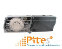
6. Zero-Max Stepless Speed Changers
These are one-way clutch-type stepless speed changers that instantly go from zero to maximum RPM. To change speed, simply operate the very responsive speed-change lever. Thanks to a creative construction that transmits rotation with a link mechanism and one-way clutch mechanism, the speed change ratio is a high 1:12, and there are no restrictions on mounting direction. Zero-Max speed changers are available as stand-alones or combined with motors.
List of Products:
S Models
As the name implies, these are one-way clutch-type stepless speed changers that instantly go from zero to maximum RPM.Thanks to a creative construction that transmits rotation with a link mechanism and one-way clutch mechanism, they are compact and lightweight, their speed change ratio is a high 1:12, and they have no restrictions on mounting direction.
· Standard applied motor output 0.2 kW to 0.4 kW (4-pole)
· Rated output shaft torque 1.38 N・m to 6.90 N・m
· Output shaft rotation speed 0 to 300,315 min-1/50 Hz, 0 to 360,380 min-1/60 Hz
[Specifications]
|
Model |
E1 |
E2 |
JK1 |
JK2 |
Y1 |
Y2 |
|
|
Output shaft rotation direction* |
Counterclockwise |
Clockwise |
Counterclockwise |
Clockwise |
Counterclockwise |
Clockwise |
|
|
Rated output shaft torque |
[N・m] |
1.38 |
1.38 |
2.88 |
2.88 |
6.90 |
6.90 |
|
Output shaft rotation speed |
[min-1] |
0~300 |
0~300 |
0~300 |
0~300 |
0~330 |
0~330 |
|
0~360 |
0~360 |
0~360 |
0~360 |
0~400 |
0~400 |
||
|
Mass |
[kg] |
1.4 |
1.4 |
1.9 |
1.9 |
4.8 |
4.8 |
MS Models
These models are ZERO-MAX stepless speed-changer stand-alones pre-combined with motors. No motor connection design is needed.There are two types of motor outputs: 0.2 kW and 0.4 kW (4-pole). There are three sizes by output shaft rated torque as well as two types by output shaft rotation direction.
· Standard applied motor output 0.2 kW to 0.4 kW (4-pole)
· Rated output shaft torque 1.38 N・m to 6.90 N・m
· Output shaft rotation speed 0 to 300,330 min-1/50 Hz, 0 to 360,400 min-1/60 Hz
[Specifications]
|
Model |
M3-E1 |
M3-E2 |
M3-JK1 |
M3-JK2 |
M3-Y1 |
M3-Y2 |
|
|
Output shaft rotation direction* |
Counterclockwise |
Clockwise |
Counterclockwise |
Clockwise |
Counterclockwise |
Clockwise |
|
|
Rated output shaft torque |
[N・m] |
1.38 |
1.38 |
2.88 |
2.88 |
6.90 |
6.90 |
|
Output shaft rotation speed |
[min-1]50Hz |
0~300 |
0~300 |
0~300 |
0~300 |
0~330 |
0~330 |
|
[min-1]60Hz |
0~360 |
0~360 |
0~360 |
0~360 |
0~400 |
0~400 |
|
|
Motor specifications |
[kW](4P) |
0.2 |
0.2 |
0.2 |
0.2 |
0.4 |
0.4 |
|
Mass |
[kg] |
7.5 |
7.5 |
8.3 |
8.3 |
14.3 |
14.3 |
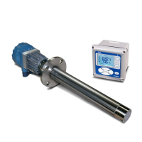
7. Miki Pulley DC Motor – Động cơ / Mô tơ DC
https://www.mikipulley.co.jp/EN/Products/SpeedChangersAndReducers/DCMotors/index.html
These are stepless variable motors using static Ward Leonard control that combine separately excited DC motors (ideal for continuous speed variation) with SCR controllers that can control the motor using tiny electrical signals of just a few mA. Speed variation is continuous from low speed to high, and with stable RPM. With excellent control response and high rotation precision (±2%) as well, their operation is extremely simple.
List of Products:
DC Motor – Động cơ / Mô tơ DC - SCD Series
These power supplies can use ordinary 100 V AC or 200 V AC current at either 50 Hz or 60 Hz. Select any speed using the speed setter on the control panel. This is a high-performance series that can use feedback control when a tachometer generator is installed on the motor.
· Rated output 0.2 kW to 3.7 kW
· Power supply voltage Single-phase 100 or 200 V/50 Hz, 100 or 200 V/60 Hz
· Speed change range 80 min.-1 to 2500 min.-1
[Specifications]
|
Model |
Motor |
SCD-100/100-E |
SCD-100/200-E |
SCD-200/100-E |
SCD-200/200-E |
SCD-400-E |
SCD-750-E |
SCD-1500-E |
SCD-2200-E |
SCD-3700-E |
|
|
Control panel |
SCD-100/100-Y |
SCD-100/200-Y |
SCD-200/100-Y |
SCD-200/200-Y |
SCD-400-Y |
SCD-750-Y |
SCD-1500-Y |
SCD-2200-Y |
SCD-3700-Y |
||
|
Rated output |
[kW] |
0.1 |
0.1 |
0.2 |
0.2 |
0.4 |
0.75 |
1.5 |
2.2 |
3.7 |
|
|
Rated torque |
[N・m] |
0.39 |
0.39 |
0.78 |
0.78 |
1.56 |
2.92 |
8.34 |
12.20 |
20.60 |
|
|
Rotation range |
[min-1] |
0~2500 |
0~1750 |
||||||||
|
Speed change range |
[min-1] |
80~2500 |
60~1750 |
||||||||
|
Power supply (AC) |
Voltage |
[V] |
100 |
200 |
100 |
200 |
200 |
200 |
200 |
200 |
200 |
|
Frequency/phase |
Single-phase, 50 Hz/60 Hz |
||||||||||
|
Allowable voltage fluctuation range |
±10% |
||||||||||
|
Current *1 |
[A] |
2.3 |
1.2 |
4.5 |
2.3 |
4.5 |
9.0 |
18 |
27 |
40 |
|
|
Output (DC) |
Armature voltage |
[V] |
80 |
160 |
80 |
160 |
160 |
160 |
160 |
160 |
160 |
|
Armature current |
[A] |
1.7 |
0.85 |
3.2 |
1.6 |
3.0 |
6.0 |
11.5 |
17.5 |
26.2 |
|
|
Magnetic field voltage |
[V] |
90 |
180 |
90 |
180 |
180 |
180 |
180 |
180 |
180 |
|
|
Magnetic field current |
[A] |
0.09 |
0.17 |
0.40 |
0.22 |
0.28 |
0.27 |
0.55 |
0.58 |
0.69 |
|
|
Motor type |
Closed C flange |
Dripproof C flange |
|||||||||
|
Rotor moment of inertia |
[kg・m2] |
0.0010 |
0.0010 |
0.0016 |
0.0016 |
0.004 |
0.004 |
0.015 |
0.026 |
0.043 |
|
|
Fuse |
Armature side *2 |
FU1 [A] |
10 |
10 |
10 |
10 |
10 |
16 |
30 |
50 |
100 |
|
FU2 [A] |
|||||||||||
|
Magnetic field side |
FU3 [A] |
0.5 |
0.5 |
0.5 |
0.5 |
0.5 |
0.5 |
1.0 |
1.0 |
1.0 |
|
|
FU4 [A] |
- |
- |
- |
- |
0.5 |
0.5 |
0.5 |
0.5 |
0.5 |
||
|
Control method |
Consistent speed control by constant voltage, IR compensation and magnetic field temperature compensation |
||||||||||
|
Components |
DC motor/control board |
DC motor/control board |
DC motor/control board |
DC motor/control board |
DC motor/control board |
DC motor/control board |
DC motor/control board |
DC motor/control board |
DC motor/control board |
||
|
Standard operations specifications |
Power supply switch/speed setter |
||||||||||
|
Carbon brush |
Model / Quantity |
Model / Quantity |
SCD-100-BL / Qty. 2 |
SCD-400-BL / Qty. 4 |
SCD-1500-BL / Qty. 2 |
||||||
|
Dimensions |
[mm] |
6×8×20 (H×W×L) |
8×6×24 (H×W×L) |
10×25×35 (H×W×L) |
|||||||
|
Control board mass |
[kg] |
3.0 |
4.5 |
8.4 |
|||||||
|
Motor mass |
[kg] |
13.2 |
17.5 |
23.8 |
24.0 |
43 |
50 |
63 |
|||
DC Motor – Động cơ / Mô tơ DC - SYD Series
These power supplies can use ordinary 100 V AC or 200 V AC current at either 50 Hz or 60 Hz. Select any speed using the speed setter on the control panel. This is an inexpensive series that limits functions to speed control.
· Rated output 0.2 kW to 1.5 kW
· Power supply voltage Single-phase 100 V or 200 V/50 Hz, 100 V or 200 V/60 Hz
· Speed change range 125 min.-1 to 2500 min.-1
[Specifications]
|
Model |
Motor |
SYD-100/100-E |
SYD-100/200-E |
SYD-200/100-E |
SYD-200/200-E |
SYD-400-E |
SYD-750-E |
SYD-1500-E |
|
|
Control panel |
SYD-100/100-□ |
SYD-100/200-□ |
SYD-200/100-□ |
SYD-200/200-□ |
SYD-400-□ |
SYD-750-□ |
SYD-1500-□ |
||
|
Rated output |
[kW] |
0.1 |
0.1 |
0.2 |
0.2 |
0.4 |
0.75 |
1.5 |
|
|
Rated torque |
[N・m] |
0.39 |
0.39 |
0.78 |
0.78 |
1.56 |
2.92 |
5.84 |
|
|
Rotation range |
[min-1] |
0~2500 |
|||||||
|
Speed change range |
[min-1] |
125~2500 |
|||||||
|
Power supply (AC) |
Voltage |
[V] |
100 |
200 |
100 |
200 |
200 |
200 |
200 |
|
Frequency/phase |
Frequency/phase |
Single phase, 50/60 Hz |
|||||||
|
Allowable voltage fluctuation range |
Allowable voltage fluctuation range |
±10% |
|||||||
|
Current *1 |
[A] |
2.3 |
1.2 |
4.5 |
2.3 |
4.5 |
9.0 |
18.0 |
|
|
Output (DC) |
Armature voltage |
[V] |
80 |
160 |
80 |
160 |
160 |
160 |
160 |
|
Armature current |
[A] |
1.7 |
0.85 |
3.2 |
1.6 |
3.0 |
6.0 |
11.5 |
|
|
Magnetic field voltage |
[V] |
85 |
175 |
85 |
175 |
175 |
175 |
175 |
|
|
Magnetic field current |
[A] |
0.09 |
0.14 |
0.09 |
0.17 |
0.23 |
0.27 |
0.38 |
|
|
Motor type |
Fully-closed C flange |
Drip-proof C flange |
|||||||
|
Rotor moment of inertia |
[kg・m2] |
0.0010 |
0.0010 |
0.0016 |
0.0016 |
0.0016 |
0.004 |
0.007 |
|
|
Fuse |
Armature side *2 |
FU1 [A] |
10 |
16 |
20 |
||||
|
Magnetic field side |
FU2 [A] |
0.5 (glass tube) |
|||||||
|
Control method |
Consistent speed control by constant voltage, IR compensation and magnetic field temperature compensation |
||||||||
|
Components |
DC motor, control panel |
||||||||
|
Standard operating specifications |
Power supply switch/speed setter |
||||||||
|
Carbon brush |
Model/number of brushes |
SCD-100-BL / Qty. 2 |
SYD-400-BL / Qty. 2 |
SCD-400-BL / Qty. 4 |
|||||
|
Dimensions |
[mm] |
6×8×20 (H×W×L) |
8×6×24 (H×W×L) |
||||||
|
Control board mass |
[kg] |
1.6 |
1.6 |
1.6 |
1.6 |
1.6 |
1.7 |
3.8 |
|
|
Motor mass |
[kg] |
10.5 |
13.2 |
16.5 |
24.0 |
36.0 |
|||
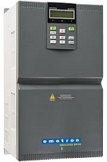
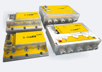
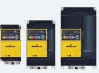
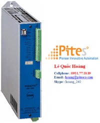
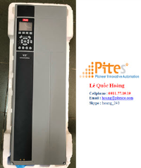
8. Miki Pulley Inverter – Biến tần
https://www.mikipulley.co.jp/EN/Products/Inverters/VSeriesInverters/InverterV7/index.html
Our V7 series inverters employ unique design ideas honed over years of experience. Induction motors can be operated with optimal speed control thanks to a full range of functions, simple operation, excellent environmental resistance, and compact design.
[Specifications]
|
Type |
V7-01-4 |
V7-02-4 |
V7-04-4 |
V7-07-4 |
V7-15-4 |
V7-22-4 |
V7-37-4 |
|
|
|
Standard applied motor output[kW] |
0.1 |
0.2 |
0.4 |
0.75 |
1.5 |
2.2 |
3.7 |
|
Output rating |
Rated capacity[kVA] |
0.3 |
0.57 |
1.1 |
1.9 |
3.0 |
4.2 |
6.5 |
|
Voltage[V] |
Three-phase, 200 to 240 V (with AVR function) |
|||||||
|
Rated current[A] |
0.8(0.7) |
1.5(1.4) |
3.0(2.5) |
5.0(4.2) |
8.0(7.0) |
11.0(10.0) |
17.0(16.5) |
|
|
Rated overload current |
150%-1 min or 200%-0.5 s of the rated output current |
|||||||
|
Rated frequency[Hz] |
50・60 |
|||||||
|
Input voltage |
Number of phases, voltage, frequency |
Three-phase, 200 to 240 V, 50/60 Hz |
||||||
|
Allowable variations of voltage and frequency |
Voltage: +10 to -15% (unbalance between phases: within 2% (* 10)) Frequency: +5 to -5% |
|||||||
|
Rated input current (with DCR)[A] |
0.57 |
0.93 |
1.6 |
3.0 |
5.7 |
8.3 |
14.0 |
|
|
Rated input current (without DCR)[A] |
1.1 |
1.8 |
3.1 |
5.3 |
9.5 |
13.2 |
22.2 |
|
|
Required power supply capacity[kVA] |
0.2 |
0.3 |
0.6 |
1.1 |
2.0 |
2.9 |
4.9 |
|
|
Braking |
Braking torque[%] |
150 |
150 |
100 |
100 |
50 |
30 |
30 |
|
DC braking |
Braking start frequency: 0.0 to 60.0 Hz, braking time: 0.0 to 30.0 s, braking level: 0 to 100% |
|||||||
|
Braking transistor |
- |
Built-in |
||||||
|
Structure/Methods |
Applicable safety standard |
UL508C IEC 61800-5-1:2007 |
||||||
|
Protection structure (IEC60529) |
IP20 enclosure UL open type |
|||||||
|
Cooling method |
Self-cooling |
Fan cooling |
||||||
|
Environment |
Operating atmosphere |
Indoor with no exposure to corrosive gases, dust, oil mist (pollution degree 2 (IEC 60664-1:2007)) or direct sunlight |
||||||
|
Ambient temperature[℃] |
Open -10 to 50 |
|||||||
|
Ambient humidity |
5 to 95%RH |
|||||||
|
Altitude |
1,000 m or below: No power reduction; 1001 to 1500 m: 0.97, 1501 to 2000 m: 0.95; 2001 to 2500 m: 0.91; 2501 to 3000 m: 0.88 |
|||||||
|
Vibration |
3 mm: 2 to 9 Hz or less; 9.8 m/s2: 9 to 20 Hz or less; 2 m/s2: 20 to 55 Hz or less; 1 m/s2: 55 to 200 Hz or less |
|||||||
|
Storage temperature[℃] |
-25 to 70 |
|||||||
|
Storage humidity |
5 to 95%RH |
|||||||
|
|
Mass[kg] |
0.6 |
0.6 |
0.7 |
0.8 |
1.7 |
1.7 |
2.5 |
* The rated output current shown is for a carrier frequency (function code F26) set to 3 kHz or less. Use the current shown in parentheses or less if the carrier frequency is set to 4 kHz or more or if the operating ambient temperature is more than 40℃
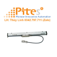
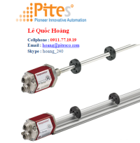
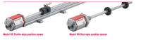
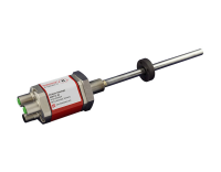
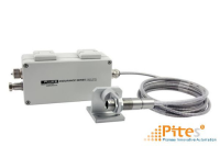
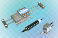
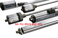
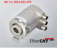
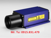
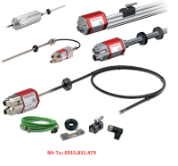
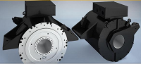
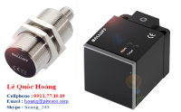
9. Miki Pulley Linear Shaft Drives – Bô truyền động bằng trục tuyến tính
https://www.mikipulley.co.jp/EN/Products/LinearShaftDrive/LinearShaftDrive/SHM+SHD/index.html
These new cylindrical linear motor systems were designed to enable driving with the simplest possible system. They detect position using flux generated by the shaft, so they can operate without external position sensors. The drivers also have built-in positioning functions that enable relatively complex positioning operations.
Application: Optical equipment/Semiconductor production equipment/Food machinery/Inspection equipment
Basic Specification:
· Rated thrust 11 N to 118 N
· Shaft diameter φ16 mm,φ25 mm
· Maximum stroke 1045 mm
Moving Part Specification :
|
Model |
SHM-162 |
SHM-163 |
SHM-165 |
SHM-252 |
SHM-254 |
SHM-256 |
SHM-258 |
|
No. of coil sets |
2 |
3 |
5 |
2 |
4 |
6 |
8 |
|
Rated thrust |
11 N |
16 N |
25 N |
28 N |
59 N |
90 N |
118 N |
|
Max. thrust |
51 N |
75 N |
117 N |
126 N |
267 N |
403 N |
532 N |
|
Max. speed |
4000 mm/s |
4000 mm/s |
4000 mm/s |
3500 mm/s |
2600 mm/s |
||
|
Rated current |
0.64 A rms |
1.2 A rms |
|||||
|
Max. current |
3.0 A rms |
5.6 A rms |
|||||
|
Time rating |
Continuous |
||||||
|
Ambient temperature |
0~40 ℃ |
||||||
|
Ambient humidity |
80% relative humidity or under (with no condensation) |
||||||
|
Insulating resistance |
500 VDC 10 M Ω or more |
||||||
|
Dielectric strength voltage |
1,500 VAC for 1 minute |
||||||
|
Heat resistance class |
Class F (coil part) |
||||||
|
Structure |
Fully-closed, self-cooling |
||||||
|
Shaft unit mass |
0.0015kg/mm |
0.0037kg/mm |
|||||
|
Moving part mass |
0.25 kg |
0.33 kg |
0.50 kg |
0.70 kg |
1.10 kg |
1.60 kg |
2.00 kg |
Drive Specification:
|
Model |
SHD-06-162 |
SHD-06-163 |
SHD-06-165 |
|
|
No. of coil sets |
2 |
3 |
5 |
|
|
Input voltage |
Main power supply: Three-phase 200 VAC, Control power supply: Single-phase 200 VAC |
|||
|
Input power supply range |
AC 200~230 V +10~-15 % 50/60 Hz ±5 % |
|||
|
Rated continuous output current |
0.64 A rms |
|||
|
Max. current (limit) |
3.0 A rms |
|||
|
Max. instantaneous current (peak value) |
6.0 A peak |
|||
|
Power supply equipment capacity |
0.6 kVA |
|||
|
Position command pulse input |
Signal |
Line driver signal |
||
|
Input method |
Select one from 2-pulse, 1-pulse, and 2-phase pulse |
|||
|
Max. frequency |
4M pulses/s |
|||
|
Input signal |
Total 16 dedicated inputs and general-purpose inputs |
|||
|
Output signal |
<CONCAT>Total 16 dedicated outputs and general-purpose outputs |
|||
|
Limit function |
Speed limit, thrust limit, and movable range limit |
|||
|
Protection function |
Overload, overcurrent, overvoltage, sensor disconnection, memory error |
|||
|
Built-in positioning function |
Number of positioning points: 32, Number of speed settings: 10 |
|||
|
Support Software |
Parameter configuration, monitor display, program editing/configuration, saving data and transferring auto-tuning data to driver |
|||
|
Ambient temperature |
0 ~ 40 ℃ (with no freezing) |
|||
|
Ambient humidity |
80% relative humidity or under (with no condensation) |
|||
|
Mass |
1.1 kg |
|||
How to Place order of Miki Pulley Linear Shaft Drives

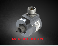
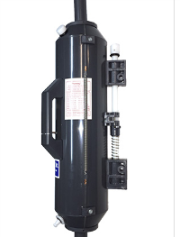
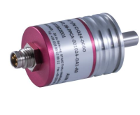
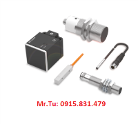
10. Miki Pulley Rotation speed Indicator – Bộ hiển thị tốc độ quay
https://www.mikipulley.co.jp/EN/Products/RotationSpeedIndicators/index.html
Use these indicators to show RPM by mounting them on the handle or shaft to be read. On the weighted model, a needle moves, while on the differential model, a dial moves. These indicators are not only accurate, they are also attractive, improving the appearance of machinery.
Product lists:
SD stand-alones Indicator
|
Model |
Structure |
Number of needles Số Kim chỉ |
Rotation ratio Tỉ lệ vòng quay |
Mass [kg] |
|
SD-28A-4-L SD-28A-4-R |
Weight Type |
1 |
1/4 |
0.06 |
|
SD-28B-4-L SD-28B-4-R |
Weight Type |
2 |
1/4 |
0.06 |
|
SD-38B-4-L SD-38B-4-R SD-38B-9-L SD-38B-9-R |
Weight Type |
1 |
1/4, 1/9 |
0.10 |
|
SD-38A-4-L SD-38A-4-R SD-38A-9-L SD-38A-9-R |
Weight Type |
2 |
1/4, 1/9 |
0.10 |
|
SD-53A-4-L SD-53A-4-R SD-53A-5-L SD-53A-5-R SD-53A-6-L SD-53A-6-R SD-53A-9-L SD-53A-9-R SD-53A-12-L SD-53A-12-R SD-53A-16-L SD-53A-16-R SD-53A-25-L SD-53A-25-R
|
Weight Type |
1 |
1/4, 1/5, 1/6, 1/9, 1/12, 1/16, 1/25 |
0.075 |
|
SD-53B-4-L SD-53B-4-R SD-53B-5-L SD-53B-5-R SD-53B-6-L SD-53B-6-R SD-53B-9-L SD-53B-9-R SD-53B-12-L SD-53B-12-R SD-53B-16-L SD-53B-16-R SD-53B-25-L SD-53B-25-R |
Weight Type |
2 |
1/4, 1/5, 1/6, 1/9, 1/12, 1/16, 1/25 |
0.075 |
|
SD-75A-4-L SD-75A-4-R SD-75A-5-L SD-75A-5-R SD-75A-6-L SD-75A-6-R SD-75A-9-L SD-75A-9-R SD-75A-12-L SD-75A-12-R SD-75A-16-L SD-75A-16-R SD-75A-25-L SD-75A-25-R SD-75A-36-L SD-75A-36-R SD-75A-40-L SD-75A-40-R SD-75A-49-L SD-75A-49-R SD-75A-64-L SD-75A-64-R |
Weight Type |
1 |
1/4, 1/5, 1/6, 1/9, 1/12, 1/16, 1/25, 1/36, 1/40, 1/49, 1/64 |
0.135 |
|
SD-75B-4-L SD-75B-4-R SD-75B-5-L SD-75B-5-R SD-75B-6-L SD-75B-6-R SD-75B-9-L SD-75B-9-R SD-75B-12-L SD-75B-12-R SD-75B-16-L SD-75B-16-R SD-75B-25-L SD-75B-25-R SD-75B-36-L SD-75B-36-R SD-75B-40-L SD-75B-40-R SD-75B-49-L SD-75B-49-R SD-75B-64-L SD-75B-64-R |
Weight Type |
2 |
1/4, 1/5, 1/6, 1/9, 1/12, 1/16, 1/25, 1/36, 1/40, 1/49, 1/64 |
0.135 |
*The scale dial is available for all types with clockwise (R type) or counterclockwise (L type) direction.
*Weight type: Turning the handle (case) moves the needle in the same direction as the turning direction of the handle.
How to order:

SD with handles Indicator for SD-53 & SD75 only
|
Model |
Structure |
Number of needles |
Rotation ratio |
|
SD-53A |
Weight Type |
1 |
1/4, 1/5, 1/6, 1/9, 1/12, 1/16, 1/25 |
|
SD-53B |
Weight Type |
2 |
1/4, 1/5, 1/6, 1/9, 1/12, 1/16, 1/25 |
|
SD-75A |
Weight Type |
1 |
1/4, 1/5, 1/6, 1/9, 1/12, 1/16, 1/25, 1/36, 1/40, 1/49, 1/64 |
|
SD-75B |
Weight Type |
2 |
1/4, 1/5, 1/6, 1/9, 1/12, 1/16, 1/25, 1/36, 1/40, 1/49, 1/64 |
*The scale dial is available for all types with clockwise (R type) or counterclockwise (L type) direction.
*Weight type: Turning the handle (case) moves the needle in the same direction as the turning direction of the handle.
|
Model |
A |
B |
C |
E |
F |
G |
H |
J |
K |
L |
N |
D |
|
|
Std. bore diameter |
Max. bore diameter |
||||||||||||
|
SD-53□-66-□-□□ |
66 |
- |
- |
- |
23 |
22.5 |
17 |
16.5 |
45.5 |
- |
40 |
10 |
28 |
|
SD-53□-80-□-□□ |
80 |
- |
- |
- |
15 |
35 |
21 |
19 |
50 |
- |
32 |
15 |
20 |
|
SD-53□-140-□-□□ |
140 |
66 |
62 |
18 |
16 |
46 |
30 |
28 |
62 |
128 |
40 |
20 |
28 |
|
SD-75□-125-□-□□ |
125 |
- |
- |
- |
20 |
40 |
30 |
25 |
60 |
- |
40 |
20 |
28 |
|
SD-75□-160-□-□□ |
160 |
66 |
71 |
18 |
16 |
47 |
30 |
33 |
63 |
129 |
40 |
20 |
28 |
|
SD-75□-180-□-□□ |
180 |
85 |
80 |
22 |
17 |
51 |
35 |
31 |
68 |
153 |
40 |
20 |
28 |
|
SD-75□-250-□-□□ |
250 |
107 |
112 |
28 |
22 |
56 |
42 |
35 |
78 |
185 |
55 |
20 |
35 |
*The tolerance for the handle bore diameter is H8.
How to order:

SD Differential Models
|
Model |
Structure |
indicators |
Speed ratio |
Mass [kg] |
|
SD-50-20-R SD-50-20-L |
Differential Type |
- |
1/20 |
0.06 |
|
SD-100-25-R SD-100-25-L SD-100-50-R SD-100-50-L |
Differential Type |
- |
1/25,1/50 |
0.27 |
*There is a type with no scale on the dial (N type) only for SD-50 and SD-100.
*Differential type: Turning the main moving plate (handle) moves the dial in the same direction as the turning direction of the main moving plate.
How to order:

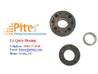
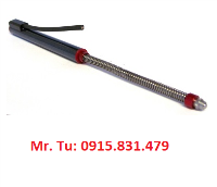
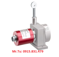
11. Miki Pulley Torque Limiter – Bộ giới hạn / hạn chế momen xoắn
https://www.mikipulley.co.jp/EN/Products/TorqueLimiter/index.html
These devices reliably detect overloads and isolate input and output by removing the drive key from the groove. Once the overload is resolved, operation can continue automatically at the same torque from the same indexing position. Torque is set using a built-in torque spring, so there is no troublesome fine-tuning.
Product List:
Torque Limiters TT(01) Types Specifications
The TT-01 type is used for two-shaft butt connection and also serves as a flexible coupling.
|
Type |
Size |
Set torque value [N・m] |
Misalignment |
Max. rotation speed [min-1] |
Moment of inertia [kg・m2] |
Mass [kg] |
|||||||||
|
Spring color |
Parallel |
Angular |
|||||||||||||
|
Colorless |
Blue |
Red |
Yellow |
White |
Gray |
Green |
Brown* |
Colorless* |
[mm] |
[°] |
|||||
|
TT-1X-01 |
1X |
0.2 |
0.5 |
1.0 |
1.5 |
2.0 |
2.5 |
3.0 |
3.5 |
4.0 |
0.2 |
0.5 |
1800 |
0.06×10⁻³ |
0.3 |
|
TT-2-01 |
2 |
1 |
2 |
3 |
4 |
5 |
6 |
7 |
8 |
10 |
0.2 |
0.5 |
1800 |
0.26×10⁻³ |
0.7 |
|
TT-2X-01 |
2X |
2 |
3 |
5 |
8 |
10 |
12 |
15 |
18 |
20 |
0.2 |
0.5 |
1800 |
0.52×10⁻³ |
1.0 |
|
TT-3-01 |
3 |
5 |
8 |
10 |
15 |
20 |
25 |
30 |
35 |
40 |
0.2 |
0.5 |
1800 |
1.23×10⁻³ |
1.5 |
|
TT-3X-01 |
3X |
10 |
16 |
20 |
30 |
40 |
50 |
60 |
70 |
80 |
0.2 |
0.5 |
1800 |
1.94×10⁻³ |
2.7 |
|
TT-4X-01 |
4X |
20 |
30 |
50 |
80 |
100 |
120 |
150 |
180 |
200 |
0.2 |
0.5 |
500 |
14.8×10⁻³ |
6.3 |
*The above set torque values listed are measured at a speed of 1500 min-1.
*Use components with larger dimensions for applications with the torque marked by [*] requiring enhanced reliability.
Torque Limiters TT(03) Types Specifications
The TT-03 type is used for wrapping. The shaft is inserted into the hub, and the pulley, gears and the like are set in the housing.
|
Type |
Size |
Set torque value [N・m] |
Max. rotation speed [min-1] |
Moment of inertia [kg・m2] |
Mass [kg] |
||||||||
|
Spring color |
|||||||||||||
|
Colorless |
Blue |
Red |
Yellow |
White |
Gray |
Green |
Brown* |
Colorless* |
|||||
|
TT-1X-03 |
1X |
0.2 |
0.5 |
1.0 |
1.5 |
2.0 |
2.5 |
3.0 |
3.5 |
4.0 |
1800 |
0.09×10⁻³ |
0.4 |
|
TT-2-03 |
2 |
1 |
2 |
3 |
4 |
5 |
6 |
7 |
8 |
10 |
1800 |
0.31×10⁻³ |
0.8 |
|
TT-2X-03 |
2X |
2 |
3 |
5 |
8 |
10 |
12 |
15 |
18 |
20 |
1800 |
0.66×10⁻³ |
1.1 |
|
TT-3-03 |
3 |
5 |
8 |
10 |
15 |
20 |
25 |
30 |
35 |
40 |
1800 |
1.59×10⁻³ |
1.7 |
|
TT-3X-03 |
3X |
10 |
16 |
20 |
30 |
40 |
50 |
60 |
70 |
80 |
1800 |
2.43×10⁻³ |
3.0 |
|
TT-4X-03 |
4X |
20 |
30 |
50 |
80 |
100 |
120 |
150 |
180 |
200 |
500 |
15.8×10⁻³ |
6.5 |
*The above set torque values listed are measured at a speed of 1500 min-1.
*Use components with larger dimensions for applications with the torque marked by [*] requiring enhanced reliability.
12. Miki Pulley Suspension Units – Thiết bị giảm xóc
https://www.mikipulley.co.jp/EN/Products/ROSTA/RubberSuspension/index.html
With their unique principles and construction, these multipurpose, versatile shock absorbers simultaneously combine the functions of spring, damper, and bearing in one unit. They are composed of metal inner and outer shells and a cylindrical column of rubber. The cylindrical rubber is press-fitted into the inner and outer shells, which have a displacement of 45°. With non-linear spring characteristics, the cylindrical rubber is compressed as it rolls, actuating it, which reliably transmits rocking motion while simultaneously absorbing vibration and noise. With little deformation over time, it boasts excellent durability under heavy loads.
Product List:
Thiết bị giảm xóc DR Models- Suspension Unit
The DR models are the basic standard ROSTA rubber springs. Choose a combination of metal outer shell and metal or aluminum alloy inner shell for your application and mounting method.They can be used for an assortment of applications, including disc springs for general machinery, elastic guides, tensioners, and flexible stoppers.
· Torque load range 0 N・m to 2160 N・m
· Operating temperature -40℃ to 80℃
[Specifications & Dimensions]

|
Model |
Dimensions |
Torque at torsional angle [N•m] |
||||||||||
|
A |
C |
E |
L |
L1±0.2 |
T+0.50 |
5° |
10° |
15° |
20° |
25° |
30° |
|
|
DR-S-11X20 |
20+0.3-0.1 |
8+0.250 |
- |
20 |
25 |
- |
0.4 |
1.0 |
1.6 |
2.4 |
3.5 |
4.8 |
|
DR-S-11X30 |
20+0.3-0.1 |
8+0.250 |
- |
30 |
35 |
- |
0.5 |
1.4 |
2.4 |
3.7 |
5.2 |
7.2 |
|
DR-S-11X50 |
20+0.3-0.1 |
8+0.250 |
- |
50 |
55 |
- |
0.8 |
2.4 |
4.1 |
6.1 |
8.6 |
12.0 |
|
DR-S-15X25 |
27+0.40 |
11+0.250 |
10±0.2 |
25 |
30 |
5 |
0.7 |
1.6 |
2.6 |
4.0 |
5.7 |
8.2 |
|
DR-S-15X40 |
27+0.40 |
11+0.250 |
10±0.2 |
40 |
45 |
5 |
1.1 |
2.5 |
4.2 |
6.4 |
9.2 |
13.2 |
|
DR-S-15X60 |
27+0.40 |
11+0.250 |
10±0.2 |
60 |
65 |
5 |
1.6 |
3.8 |
6.3 |
9.6 |
13.8 |
19.8 |
|
DR-S-18X30 |
32+0.3-0.1 |
12+0.250 |
12±0.3 |
30 |
35 |
6 |
1.9 |
4.5 |
7.5 |
11.0 |
15.0 |
20.6 |
|
DR-S-18X50 |
32+0.3-0.1 |
12+0.250 |
12±0.3 |
50 |
55 |
6 |
3.2 |
7.5 |
12.5 |
18.3 |
25.0 |
34.4 |
|
DR-S-18X80 |
32+0.3-0.1 |
12+0.250 |
12±0.3 |
80 |
85 |
6 |
5.1 |
12.0 |
20.0 |
29.3 |
40.0 |
55.0 |
|
DR-S-27X40 |
45+0.40 |
22+0.250 |
20±0.4 |
40 |
45 |
8 |
4.7 |
10.7 |
17.5 |
26.9 |
39.5 |
57.0 |
|
DR-S-27X60 |
45+0.40 |
22+0.250 |
20±0.4 |
60 |
65 |
8 |
7.0 |
16.0 |
26.3 |
40.3 |
59.3 |
85.5 |
|
DR-S-27X100 |
45+0.40 |
22+0.250 |
20±0.4 |
100 |
105 |
8 |
11.7 |
26.7 |
43.8 |
67.2 |
98.8 |
142.5 |
|
DR-S-38X60 |
60+0.3-0.2 |
30+0.250 |
25±0.4 |
60 |
70 |
10 |
13.0 |
30.4 |
50.6 |
78.0 |
113.0 |
162.0 |
|
DR-S-38X80 |
60+0.3-0.2 |
30+0.250 |
25±0.4 |
80 |
90 |
10 |
17.3 |
40.5 |
67.5 |
104.0 |
151.0 |
216.0 |
|
DR-S-38X120 |
60+0.3-0.2 |
30+0.250 |
25±0.4 |
120 |
130 |
10 |
26.0 |
60.8 |
101.2 |
156.0 |
226.0 |
324.0 |
|
DR-S-45X80-N |
75+0.3-0.2 |
35+0.40 |
35±0.5 |
80 |
90 |
12 |
27.6 |
62.4 |
104.0 |
160.0 |
222.0 |
320.0 |
|
DR-S-45X100-N |
75+0.3-0.2 |
35+0.40 |
35±0.5 |
100 |
110 |
12 |
34.5 |
78.0 |
130.0 |
200.0 |
278.0 |
400.0 |
|
DR-S-45X150-N |
75+0.3-0.2 |
35+0.40 |
35±0.5 |
150 |
160 |
12 |
51.8 |
117.0 |
195.0 |
300.0 |
420.0 |
600.0 |
|
DR-S-50X120-N |
80+0.3-0.2 |
40+0.40 |
40±0.5 |
120 |
130 |
M12X40 |
51.0 |
133.0 |
250.0 |
395.0 |
570.0 |
780.0 |
|
DR-S-50X200-N |
80+0.3-0.2 |
40+0.40 |
40±0.5 |
200 |
210 |
M12X40 |
102.0 |
260.0 |
475.0 |
745.0 |
1070.0 |
1450.0 |
|
DR-S-50X300-N |
80+0.3-0.2 |
40+0.40 |
40±0.5 |
300 |
310 |
M12X40 |
150.0 |
385.0 |
700.0 |
1100.0 |
1590.0 |
2160.0 |
Thiết bị giảm xóc DK Models- Suspension Unit
The outer shell is a cylindrical aluminum alloy. The inner shell is a metal hollow square or aluminum alloy.It can be locked at any position on a full 360°of rotation. They can be used for an assortment of applications, including disc springs for general machinery, elastic guides, tensioners, and flexible stoppers.
· Torque load range 0 N・m to 600 N・m
· Operating temperature -40℃ to 80℃
[Specifications & Dimensions]

|
Model |
Dimensions |
Torque at torsional angle [N•m] |
||||||||||||
|
C |
D |
E |
L |
L1±0.2 |
T+0.50 |
U |
W |
5° |
10° |
15° |
20° |
25° |
30° |
|
|
DK-S-11X20 |
8+0.250 |
28+0.50.1 |
- |
20 |
25 |
- |
2.5 |
4 |
0.4 |
1.0 |
1.6 |
2.4 |
3.5 |
4.8 |
|
DK-S-11X30 |
8+0.250 |
28+0.50.1 |
- |
30 |
35 |
- |
2.5 |
4 |
0.5 |
1.4 |
2.4 |
3.7 |
5.2 |
7.2 |
|
DK-S-11X50 |
8+0.250 |
28+0.50.1 |
- |
50 |
55 |
- |
2.5 |
4 |
0.8 |
2.4 |
4.1 |
6.1 |
8.6 |
12.0 |
|
DK-S-15X25 |
11+0.250 |
36+0.50.1 |
10±0.2 |
25 |
30 |
5 |
2.5 |
5 |
0.7 |
1.6 |
2.6 |
4.0 |
5.7 |
8.2 |
|
DK-S-15X40 |
11+0.250 |
36+0.50.1 |
10±0.2 |
40 |
45 |
5 |
2.5 |
5 |
1.1 |
2.5 |
4.2 |
6.4 |
9.2 |
13.2 |
|
DK-S-15X60 |
11+0.250 |
36+0.50.1 |
10±0.2 |
60 |
65 |
5 |
2.5 |
5 |
1.6 |
3.8 |
6.3 |
9.6 |
13.8 |
19.8 |
|
DK-S-18X30 |
12+0.250 |
45+0.60.1 |
12±0.3 |
30 |
35 |
6 |
2.5 |
5 |
1.9 |
4.5 |
7.5 |
11.0 |
15.0 |
20.6 |
|
DK-S-18X50 |
12+0.250 |
45+0.60.1 |
12±0.3 |
50 |
55 |
6 |
2.5 |
5 |
3.2 |
7.5 |
12.5 |
18.3 |
25.0 |
34.4 |
|
DK-S-18X80 |
12+0.250 |
45+0.60.1 |
12±0.3 |
80 |
85 |
6 |
2.5 |
5 |
5.1 |
12.0 |
20.0 |
29.3 |
40.0 |
55.0 |
|
DK-S-27X40 |
22+0.250 |
62+0.70.1 |
20±0.4 |
40 |
45 |
8 |
3 |
6 |
4.7 |
10.7 |
17.5 |
26.9 |
39.5 |
57.0 |
|
DK-S-27X60 |
22+0.250 |
62+0.70.1 |
20±0.4 |
60 |
65 |
8 |
3 |
6 |
7.0 |
16.0 |
26.3 |
40.3 |
59.3 |
85.5 |
|
DK-S-27X100 |
22+0.250 |
62+0.70.1 |
20±0.4 |
100 |
105 |
8 |
3 |
6 |
11.7 |
26.7 |
43.8 |
67.2 |
98.8 |
142.5 |
|
DK-S-38X60 |
30+0.250 |
80+0.80.1 |
25±0.4 |
60 |
70 |
10 |
3.5 |
7 |
13.0 |
30.4 |
50.6 |
78.0 |
113.0 |
162.0 |
|
DK-S-38X80 |
30+0.250 |
80+0.80.1 |
25±0.4 |
80 |
90 |
10 |
3.5 |
7 |
17.3 |
40.5 |
67.5 |
104.0 |
151.0 |
216.0 |
|
DK-S-38X120 |
30+0.250 |
80+0.80.1 |
25±0.4 |
120 |
130 |
10 |
3.5 |
7 |
26.0 |
60.8 |
101.2 |
156.0 |
226.0 |
324.0 |
|
DK-S-45X80 |
35+0.400 |
95+1.00.1 |
35±0.5 |
80 |
90 |
12 |
4 |
8 |
27.6 |
62.4 |
104.0 |
160.0 |
222.0 |
320.0 |
|
DK-S-45X100 |
35+0.400 |
95+1.00.1 |
35±0.5 |
100 |
110 |
12 |
4 |
8 |
34.5 |
78.0 |
130.0 |
200.0 |
278.0 |
400.0 |
|
DK-S-45X150 |
35+0.400 |
95+1.00.1 |
35±0.5 |
150 |
160 |
12 |
4 |
8 |
51.8 |
117.0 |
195.0 |
300.0 |
420.0 |
600.0 |
* The sizes 45 × 80, 45 × 100, and 45 × 150 are made to order.
Thiết bị giảm xóc DO Models- Suspension Unit – Made to order – sản xuất theo yêu cầu
These models connect two basic standard ROSTA rubber springs. They have an aluminum alloy outer shell and a metal or aluminum alloy inner shell.This model links two springs, so it has a big rated torsion angle of 60°. They can be used for an assortment of applications, including disc springs for general machinery, elastic guides, tensioners, and flexible stoppers.
· Torque load range 0 N・m to 324 N・m
· Operating temperature -40℃ to 80℃
Size available:
|
Size |
A |
B |
C |
E |
F |
L |
L1±0.2 |
T+0.50 |
|
|
DO-S |
DO-A |
||||||||
|
15×25 |
15×25 |
28±0.15 |
53.5±0.2 |
11+0.250 |
10±0.2 |
25.5 |
25 |
30 |
5 |
|
15×40 |
15×40 |
28±0.15 |
53.5±0.2 |
11+0.250 |
10±0.2 |
25.5 |
40 |
45 |
5 |
|
15×60 |
15×60 |
28±0.15 |
53.5±0.2 |
11+0.250 |
10±0.2 |
25.5 |
60 |
65 |
5 |
|
18×30 |
18×30 |
34±0.15 |
65±0.2 |
12+0.250 |
12±0.3 |
31 |
30 |
35 |
6 |
|
18×50 |
18×50 |
34±0.15 |
65±0.2 |
12+0.250 |
12±0.3 |
31 |
50 |
55 |
6 |
|
18×80 |
18×80 |
34±0.15 |
65±0.2 |
12+0.250 |
12±0.3 |
31 |
80 |
85 |
6 |
|
27×40 |
27×40 |
47±0.15 |
91±0.2 |
22+0.250 |
20±0.4 |
44 |
40 |
45 |
8 |
|
27×60 |
27×60 |
47±0.15 |
91±0.2 |
22+0.250 |
20±0.4 |
44 |
60 |
65 |
8 |
|
27×100 |
27×100 |
47±0.15 |
91±0.2 |
22+0.250 |
20±0.4 |
44 |
100 |
105 |
8 |
|
38×60 |
38×60 |
63±0.20 |
123±0.3 |
30+0.250 |
25±0.4 |
60 |
60 |
70 |
10 |
|
38×80 |
38×80 |
63±0.20 |
123±0.3 |
30+0.250 |
25±0.4 |
60 |
80 |
90 |
10 |
|
38×120 |
38×120 |
63±0.20 |
123±0.3 |
30+0.250 |
25±0.4 |
60 |
120 |
130 |
10 |
*For large dimensions other than the above, please contact Miki Pulley.

13. Miki Pulley Tensioners – Thiết bị kéo căng/ Bộ căng đai
https://www.mikipulley.co.jp/EN/Products/ROSTA/Tensioner/index.html
An arm is mounted on a suspension unit and rollers and sprockets are set, enabling use in tensioning, as a pressure roller, and as a damper. With a flanged outer shell and mount that secures with a single bolt, it is easy to set. A wide range of loads can be accommodated, since the idler's mounting bore can be selected for a range of usage loads. SE models have no idler while RSE belt tensioners come with roller idlers. We also offer NSE tensioners, which come with sprocket idlers.
SE/SE-I Models Tensioners – Thiết bị kéo căng/ Bộ căng đai
These are tensioner units that integrate a metal arm with the inner shell and the outer shell with a flange.They can be mounted with a single center bolt. They can be used for an assortment of applications, such as scrapers for conveyor belts or pressure rollers in machinery.
· Torque load range 0 N to 2650 N
· Operating temperature -40℃ to 80℃
· Material SE Models : Steel , SE-I Models : Stainless
[Specifications]
|
Model |
Load range F [N] |
Max. displacement S1 [mm] |
Max. displacement S2 [mm] |
Mass [kg] |
|
|
SE |
SE-I |
||||
|
SE-11 |
0~96 |
40 |
30 |
0.20 |
- |
|
SE-15・SE-I-15 |
0~135 |
50 |
40 |
0.40 |
0.40 |
|
SE-18・SE-I-18 |
0~350 |
50 |
40 |
0.60 |
0.70 |
|
SE-27・SE-I-27 |
0~810 |
65 |
50 |
1.70 |
2.10 |
|
SE-38・SE-I-38 |
0~1500 |
88 |
70 |
3.60 |
4.10 |
|
SE-45 |
0~2650 |
113 |
90 |
6.40 |
- |
* The load range is for the normal position.
Hard position load range ≒ 1.25 x normal position load range
RSE Models Tensioners – Thiết bị kéo căng/ Bộ căng đai
These are belt tensioners that combine an SE tensioner with an aluminum alloy roller.They can be used in standard belt, timing belt, flat belt and other belt tensioners or in pressured rollers of conveyor belts and the like.
· Torque load range 0 N to 2650 N
· Operating temperature -40℃ to 80℃
[Specifications]
|
Model |
Load range F [N] |
Max. displacement S1 [mm] |
Max. displacement S2 [mm] |
Compatible belt |
Max. rotation speed [min-1] |
|
RSE-11 |
0~96 |
40 |
30 |
A |
8000 |
|
RSE-15 |
0~135 |
50 |
40 |
B |
8000 |
|
RSE-18 |
0~350 |
50 |
40 |
B |
8000 |
|
RSE-27 |
0~810 |
65 |
50 |
C |
6000 |
|
RSE-38 |
0~1500 |
88 |
70 |
- |
5000 |
|
RSE-45 |
0~2650 |
113 |
90 |
- |
4500 |
* The load range is for the normal position.
Hard position load range ≒ 1.25 x normal position load range
NSE Models Tensioners – Thiết bị kéo căng/ Bộ căng đai
These are chain tensioners that combine an SE tensioner with a sprocket idler.In addition to use as chain tensioners, they can be used as riders of chain conveyors.
· Torque load range 0 N to 2650 N
· Operating temperature -40℃ to 80℃
[Specifications]
|
Model |
Load range F [N] |
Max. displacement S1 [mm] |
Max. displacement S2 [mm] |
Compatible chain |
|
|
NSE-15 |
-35S |
0~135 |
50 |
40 |
35 |
|
-35D |
|||||
|
NSE-18 |
-35S |
0~350 |
50 |
40 |
35 |
|
-35D |
|||||
|
NSE-18 |
-40S |
0~350 |
50 |
40 |
40 |
|
-40D |
|||||
|
NSE-27 |
-50S |
0~810 |
65 |
50 |
50 |
|
-50D |
|||||
|
NSE-27 |
-60S |
0~810 |
65 |
50 |
60 |
|
-60D |
|||||
|
NSE-38 |
-80S |
0~1500 |
88 |
70 |
80 |
|
-80D |
|||||
|
NSE-45 |
-100S |
0~2650 |
113 |
90 |
100 |
|
-100D |
|||||
|
NSE-45 |
-120S |
0~2650 |
113 |
90 |
120 |
|
-120D |
|||||

14. Miki Pulley Anti-vibration Mountings– Khung chống rung
https://www.mikipulley.co.jp/EN/Products/ROSTA/Anti-VibrationMountings/index.html
These mounts control vibration in all manner of mechanical equipment. They come in ESL models (for intermediate frequencies in the 4.5-11 Hz eigenfrequency band) and V models (for relatively high frequency bands). All models can be installed in any direction and handle loads in the left, right, up, down, front and back directions.
Anti-vibration Mountings– Khung chống rung ESL Models
These are vibration-controlling mounts that combine DO model suspension units with brackets. They are suitable for eigenfrequencies of 4.5 Hz to 11 Hz, an intermediate frequency band.They allow loads in compression, tension and shear directions. They can be mounted in any direction.
· Torque load range 400 N to 6000 N
· Operating temperature -40℃ to 80℃
[Specifications]
|
Model |
Operating load range [N] Z-direction |
Max. allowable load [N] |
Natural frequency [Hz] |
Mass [kg] |
|
|
X-direction |
Y-direction |
||||
|
ESL-15 |
200-550 |
110 |
1100 |
5.8~8.2 |
0.4 |
|
ESL-18 |
450-1250 |
250 |
2500 |
5.0~7.5 |
0.6 |
|
ESL-27 |
700-2000 |
400 |
4000 |
4.5~6.2 |
1.3 |
|
ESL-38 |
1300-3800 |
760 |
7600 |
4.0~5.5 |
3.4 |
|
ESL-45 |
2200-6000 |
1200 |
12000 |
3.5~5.0 |
5.3 |
*ESL-38 and -45 are made to order.
Anti-vibration Mountings– Khung chống rung V Models
These are vibration-controlling mounts that combine suspension units with brackets. They are suitable for eigenfrequencies of 12 Hz to 30 Hz, a relatively high frequency band.They allow loads in compression, tension and shear directions. They can be mounted in any direction.
· Torque load range 800 N to 8000 N
· Operating temperature -40℃ to 80℃
[Specifications]
|
Model |
Operating load range [N] Z- and X-directions |
Max. allowable load [N] Y-direction |
Natural frequency [Hz] |
Mass [kg] |
|
V-15 |
300-800 |
160 |
23~30 |
0.3 |
|
V-18 |
600-1600 |
320 |
15~25 |
0.7 |
|
V-27 |
1300-3000 |
600 |
20~28 |
1.3 |
|
V-38-N |
2600-5000 |
1000 |
12~14 |
2.7 |
|
V-45 |
4500-8000 |
1600 |
12~15 |
4.6 |
*V-38 and -45 are made to order.
15. Miki Pulley Rocking Mountings – Khung chuyển động/ Khung lắc dọc
https://www.mikipulley.co.jp/EN/Products/ROSTA/OscillatingMountings/index.html
The rocking mounts and rocking drive heads that are used to build oscillating conveyors and vibration sieving machines can be constructed with suspension units. AU models of rocking mount can be directly mounted by flange to an oscillating conveyor of the exciting type that uses a crank motion, for example. Rod end RST models smoothly transmit the rocking motion caused by that cranking motion. Use them in combination to build the optimal design. We also provide the AB models, a mount for oscillating conveyors and vibration sieving machines that use vibrating motors. AB models can absorb vibration going to the outside, such as to floors, while they efficiently transmit the exciting force generated by the vibrating motor.
List of Products:
Rocking Mountings – Khung chuyển động/ Khung lắc dọc AU Models
AU models of rocking mount can be directly mounted by flange to an oscillating conveyor of the exciting type that uses a crank motion, for example. Rod end RST models smoothly transmit the rocking motion caused by that cranking motion. Use them in combination to build the optimal design.
· Torque load range 100 N to 5000 N
· Operating temperature -40℃ to 80℃
[Specifications]
|
Model |
Max. allowable load F [N] |
Allowable frequency at ±5°[min-1] |
Dynamic torsional stiffness [N・m/°] |
Mass [kg] |
|
AU-15-R |
100 |
640 |
0.44 |
0.2 |
|
AU-15-L |
100 |
640 |
0.44 |
0.2 |
|
AU-18-R |
200 |
600 |
1.32 |
0.4 |
|
AU-18-L |
200 |
600 |
1.32 |
0.4 |
|
AU-27-R |
400 |
560 |
2.60 |
0.7 |
|
AU-27-L |
400 |
560 |
2.60 |
0.7 |
|
AU-38-R |
800 |
530 |
6.70 |
1.55 |
|
AU-38-L |
800 |
530 |
6.70 |
1.55 |
|
AU-45-R |
1600 |
500 |
11.60 |
2.55 |
|
AU-45-L |
1600 |
500 |
11.60 |
2.55 |
|
AU-50-R |
2500 |
470 |
20.40 |
6.70 |
|
AU-50-L |
2500 |
470 |
20.40 |
6.70 |
|
AU-60-R |
5000 |
440 |
38.20 |
15.70 |
|
AU-60-L |
5000 |
440 |
38.20 |
15.70 |
Rocking Mountings – Khung chuyển động/ Khung lắc dọc RST Models
AU models of rocking mount can be directly mounted by flange to an oscillating conveyor of the exciting type that uses a crank motion, for example.Rod end RST models smoothly transmit the rocking motion caused by that cranking motion. Use them in combination to build the optimal design.
· Torque load range 400 N to 27000 N
· Operating temperature -40℃ to 80℃
[Specifications]
|
Model |
Max. allowable acceleration force F [N] |
Allowable frequency at ±5°[min-1] |
Mass [kg] |
|
RST-18-R,L |
400 |
600 |
0.2 |
|
RST-27-R,L |
1000 |
560 |
0.4 |
|
RST-38-R,L |
2000 |
530 |
1.1 |
|
RST-45-R,L |
3500 |
500 |
1.8 |
|
RST-50-R,L |
6000 |
470 |
5.5 |
|
RST-60-N-R,L |
13000 |
440 |
15.6 |
|
RST-80-N-R |
27000 |
380 |
36.7 |
*The allowable frequency at ±5°[min-1] is that at an oscillation angle of ±5°.
*The allowable torsional angle is ±5°.
*The RST-60-N-R, RST-60-N-L and RST-80-N-R are made to order.
Rocking Mountings – Khung chuyển động/ Khung lắc dọc AB/AB-I Models
These can be used as mounts for oscillating conveyors and vibration sieving machines that use vibrating motors.These combinations are very soft in the vertical direction, enabling flexible support. By using multiple units in parallel, even high capacity loads can be handled. AB models can also absorb vibration going to the outside, such as to floors, while they efficiently transmit the exciting force generated by the vibrating motor.
· Torque load range 160 N to 10000 N
· Operating temperature -40℃ to 80℃
· Material AB Models : Steel , AB-I Models : Stainless
[Specifications]
|
Model |
Operating load range [N] |
Dynamic stiffness [N/mm] |
Mass [kg] |
||
|
Vertical direction |
Horizontal direction |
AB |
AB-I |
||
|
AB-15-N AB-I-15 |
50-160(70~180) |
10 |
6 |
0.5 |
0.9 |
|
AB-18-N AB-I-18 |
120-350 |
20 |
14 |
1.2 |
1.7 |
|
AB-27-N AB-I-27 |
250-800 |
40 |
25 |
2.2 |
3.3 |
|
AB-38-N AB-I-38 |
600-1600 |
60 |
30 |
5.1 |
7.6 |
|
AB-45-N AB-I-45 |
1200-3000 |
100 |
50 |
11.5 |
13.5 |
|
AB-50-N AB-I-50 |
2500-6000 |
190 |
85 |
19.1 |
21.9 |
|
AB-50-N-2 AB-I-50-2 |
4200-10000 |
320 |
140 |
32.2 |
35.4 |
* The specifications in parentheses ( ) for the AB-15-N/AB-I-15 are the AB-I-15 values.
* The dynamic stiffness is data when the frequency is 960 min-1 and the amplitude is 8 mm under the rated load.